Camera Alignment

Use the head camera.

3 Likes

@Tom_A ,

I am experiencing the exact SAME issue and I notified support about it yesterday. I sent the the below before and after shots to support, and the notified me its something they are working on.

The worrisome thing is, before last week this machine was pretty dead on alignment. So I hope its something they can fix.

I have been doing what @takitus has suggested and laying everything out in illustrator until the alignment gets a little better.

The annoying thing is I find myself leaving a 1/4" gap around my work area to account for alignment offset, which is a waste of material.


alignment test 2

2 Likes

I’ve seen it get better in the last six months. I’ve seen it get more offset at times while there was an software change, but then it always comes back with an improvement. After the big addition of more usable area in May, that made the center part of alignment get much better. Whatever they are working on for the GFUI code, there have been improvements. But as was recently stated by support, the best way to align is the center of the machine; that doesn’t mean you shouldn’t be getting good results at the perimeter, just not sub millimeter accuracy at this point.

5 Likes

If it worked great before, that’s really super encouraging to me, since it was probably a software change that caused it. There be geometry and optics and math here…

4 Likes

When I start my other project that will have VERY tight tolerances for the top and bottom of the material, I’m planning on running a light score around the outlines just to make sure everything will appear where it should, before I laser, score, cut the final piece. It’s the only way I know to REALLY see if something is aligned properly.

3 Likes

I have never tested the accuracy of my camera, mostly because I have had great success with cutting small shapes out of scraps and never felt the need. I am also expecting that once the head camera is enabled we will have pretty extreme registration capabilities. This thread has peaked my interest in the exact tolerance of my bed camera however, so I decided to run some tests.

I created a 1" grid pattern and scored onto some scrap cardboard. The cardboard was not a very good test material however because it had both bowing/warping issues as well as I measured pretty inconsistent thicknesses ranging from .16" to .175. I used .17" as my initial value for the focus height. I placed magnets around the parameter in an effort to minimize warping issues, but there was still some areas hovering above the bed.


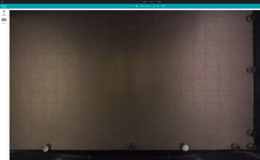
Bed image before scoring, focus set to .17"


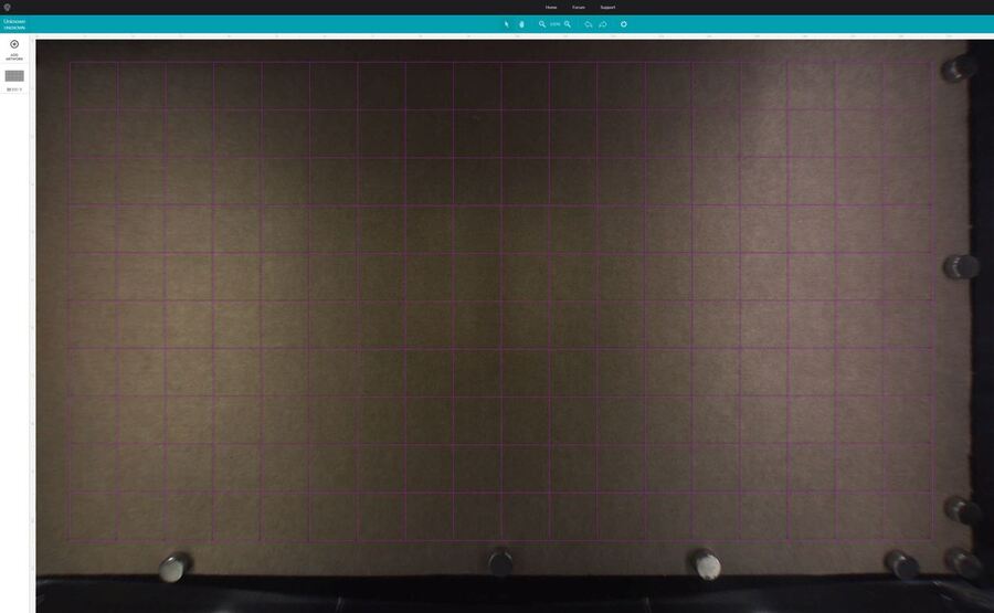
Bed image after scoring (no shifting of the grid), focus still set to .17". I could see some minor shifting so I started playing around with focus settings. I found .15" got pretty close to an overlap of the scores and the vector grid.


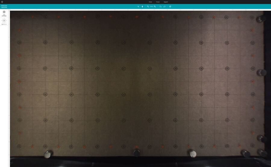
Bed image after adjusting focus to .15". I decided to bring in a target point to try to line up and then score over the grid lines now on the cardboard. I placed each one individually by eye at 200% zoom in the GFUI.


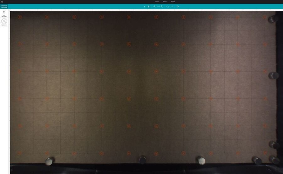
Bed image with focus at .15" and all the target points placed by eye.


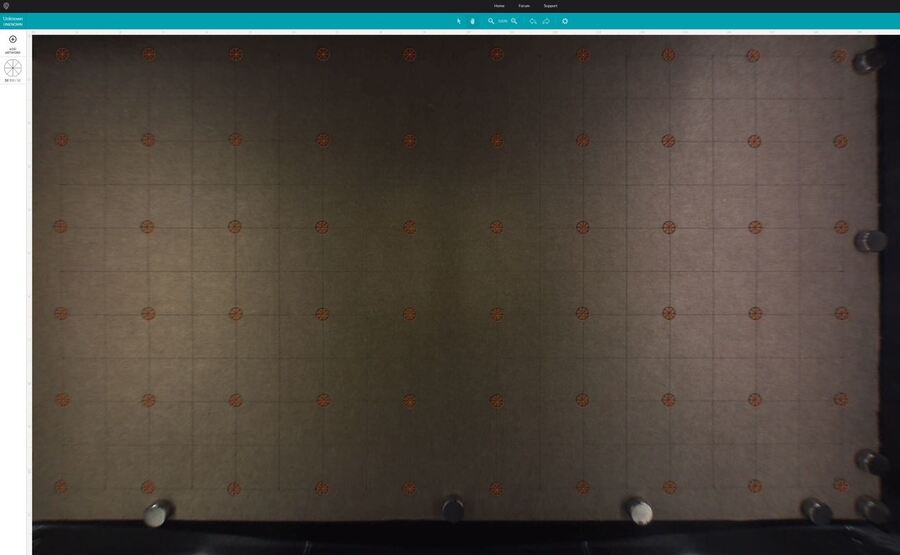
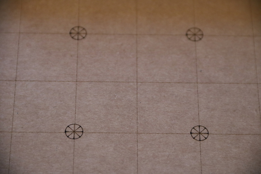
Bed image after scoring targets. Focus still set to .15".


Bed image with new targets (no circles) focus now set back to .17".


Bed image with new targets scored. There was more of a visible shift for sure.
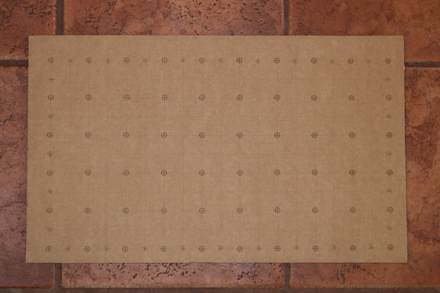

Photo of results.

IMG_3481
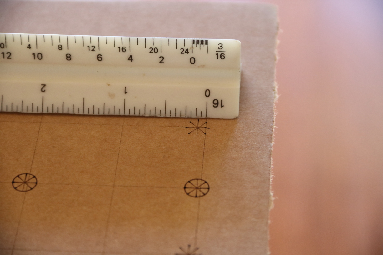
Worst case, focus set at .17". Offset less than 1/8".

IMG_3482
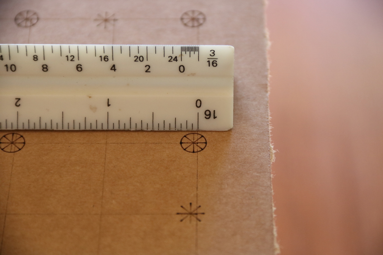
Focus set to .15". Offset less than 1/16".


Finally a shot of the four most central targets.

This test would have been more meaningful with a more consistent material like Proofgrade. That being said, should anyone wish to try to replicate on their end I will provide my SVG files.
TestGridSVGs.zip (1.9 KB)

22 Likes

Very interesting. So a 0.02" difference in height makes about 1/16" = 0.0625" difference at the edges. Probably about right as it could be three times further from the lens to the edge than it is straight down.

3 Likes

My magnets are .12" thick, yet they look like little towers in the extremes of the bed image.

3 Likes

Fantastic job testing that! :grinning:

2 Likes

I’m working on some invitations for friends of mine. The entire cardstock is 11" x 8 1/2" which will be cut down to 10" x 7". The inside right side is a 5" x 7" photo with information of their event, the left side is a cut design. There is a cut line for the previous dimensions. I can not line up the design and cut even with the photo. It’s impossible with the way the camera is now, have been lucky s few times though. I’ve even made a jig for the paper to ensure the cardstock is straight. Unfortunately, the image in the UI is not.
Reported to support.
This is a problem that obviously needs to take priority!!

This is extremely correct. A very small vertical distance will create a very large horizontal offset in the preview.

We’ve never seen this happen. Given the way the hardware works, I believe it’s unlikely - if it moves at all, it’s going to fall off.

In manufacturing, ever part has a tolerance. Machine-to-machine variation is calibrated out at the factory, though.

Indeed. It’s easy to obtain much larger or smaller values depending on the height error. (There are other sources of error, but that’s the biggest).

The nonobvious piece of the puzzle is that the height of the material has an enormous impact on the final image accuracy, and that depends on:

  • The flatness of the surface your Glowforge rests on
  • Whether the tray feet sit properly in their grooves, or if there’s a tiny bit of debris in there
  • Whether the metal grate is dead flat
  • Whether your material is dead flat
  • The material thickness, which is the only one on the list that we actually know and can compensate for.

Any tiny variation in those factors will cause a big change in your positioning accuracy.

In the future, we plan to dramatically improve this by allowing you to scan the material with the autofocus system to get a very accurate read on the material height (not thickness - the height, which is what actually matters). We also have some improvements (especially around the edges) coming from a new calibration system.

21 Likes

I’m glad to see these additional head features taken advantage of! Any progress on the use of the head cam?

2 Likes

I bet you saw this answer coming, but: we’ll let you know just as soon as we have anything ready to share. :wink:

6 Likes

As long as you keep the final “shave an a haircut” as the last of the calibration cadence :slight_smile:

ugh.

Quick update… Rita asked for testing on :proofgrade:. I decided to do the extreme corners of the available workspace. Here are my results:

Upper-left
image
Lower-left


Upper-right
image (2)
Lower-right

4 Likes

These results don’t really tell us anything without a sense of scale. How big are your targets?

That’s why I included the rulers. :wink:

3 Likes

Thanks, missed that!

1 Like

They’re easy to miss with such low contrast. I hate them as they are.
I was zoomed in to 150% for these pics. I should have made it easier by going 100% or 200%, but oh well.

3 Likes