No, you need a test reference that lives outside of the system that you’re trying to investigate.
Right now you can not tell if your lid camera is out of alignment to the case/bed or if there is an image de-warping issue, or if the camera/de-warping is working perfectly and there is some other alignment/calibration issue.
Using the same SVG file, make a physical print of the test pattern, position it in the GF, and if the lid camera image of that pattern matches up with the file loaded into the GFUI, you know the issue is NOT the camera or de-warping.
You’ve seen the tests I did like this with my machine and the camera is dead-on but the laser itself is off a little bit.
There is no alignment between the camera and the case / bed. It is between the logo on the head and the camera. So if the lid was shifted left 1" the head should set up 1" left of centre and still engrave relative to the centre of the camera image. Somehow the camera and the laser don’t point to the same spot on the bed.
Yes. They were reluctant about replacing it, stating that my earlier posts in this thread are within spec. But since my first unit was spot on, I figured the 2nd wasn’t working properly. But now that I have the third, it seems possible that my first one was the fluke as far as alignment is concerned. I could press them for yet another replacement, I suppose. But I don’t know if that’d help. SO FRUSTRATED.
Dan keeps saying it will get better with software but if they replaced yours that doesn’t look likely. The only way to fix an offset in the centre would be to recalibrate it. @dan will offsets in the centre like this be fixable in the field?
What do you measure the material thickness at and how does that compare to what Proofgrade automatically chooses for height? Perhaps this is the state of Proofgrade beta or Proofgrade will rely on laser measurements from the head when all that is sorted out.
The height shouldn’t make a significant difference in the middle of the bed where the camera is looking straight down. It will make a big difference in the corners though.
Unless the camera isn’t pointed directly straight down, and made it past QA being aimed at a small angle. Then not only would the middle be shifted to the side, but the far edges would be magnitudes off their marks as well.
I feel like there should be a calibration sheet the size of the bed that you could put in with known points so the camera could set itself up with that, So if it was angled a bit that would be taken into consideration. or even just markers in the 4 corners of the bed.
You should be able to put a blank sheet in, have GF engrave a test pattern, look at it with the camera and produce a perfect de-warp map so the image matches the pattern. It should then be accurate to about 1 camera pixel.
The actual thickness of the material will not necessarily be reflected in the settings for Proofgrade materials. I did not measure, but I would not expect them to match. Way up top you’ll see non-proofgrade testing, where I’ve both measured and set the material thickness, and you’ll see the same result.
Not too worried about it myself. Thinking that at some point if alignment continues to be an issue the company will enable a calibration pattern that a user can execute and any offset or even a distortion correction map might be saved for each unit. It’s not rocket science but may not be their first solution.
Of course that doesn’t give you accuracy down to a gnat’s butt though it could get you to where they intended to be with a lid cam.
I can’t test this right now, but if that is the afterimage that you are looking at, it is totally separate from the initial placement image, and has nothing to do with alignment. It can be off by that much. Or it can be right over the top of where you initially placed the image. I’ve had it do both - early on in the PRU testing, the afterimage was off by that much, and it didn’t matter a bit. If I sent the cut a second time, it cut precisely over the initial cut.
Lately, the afterimage on the PRU has been right on the money - or off by the amount of shadow. Again though, the afterimage has absolutely no bearing on anything. I suspect the second image might be dropping the height setting, and it “appears” to be off. You can try re-entering the height for the material in the Unknown Material slot and see if it changes the view.
But there’s an easier way to test, just send a second cut or engrave after the first one finishes. Even after you get an afterimage that looks like that one. It should be absolutely exact if you don’t move the material or try to realign the images on the screen.
If the initial placement is off by more than a quarter inch though, that does indicate a problem that you need to contact support about. Say you set up a cut a quarter of an inch from the edge of the material and it cuts off the edge instead of in far enough to be placed on the material.
This is what they had us sign off on as recipients of the first units, knowing that there were still going to be changes to the alignment. Nothing to despair over yet.
I’m baffled why you’d think that. The before and after shots are exactly the same (aside from the refreshed bed image). If yours is different I think that’s a Support issue.
Yes… That, of course, is true. If nothing changes, it does the exact same thing. It’s off by the exact same amount. Doing the same thing wrong over and over again doesn’t make it right.
It is, in some places. After I do a couple more tests, I’ll report to Support.
Having had, what I consider to be, perfect alignment in the past, I disagree.
Well it has to be unless the machine homes in between because where the origin of the coordinate system is is set when it homes on the logo.
The camera is fixed so where it looks at can’t change either. If the image of the centre of the bed moves then a bogus offset must be added to shift the image on the screen.
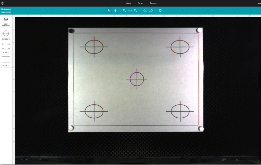
Test pattern inkjet printed onto paper. Paper pattern placed into GF. SVG file and de-warped GF lid camera image are dead-on match. This tells me there are no optical or de-warping issues with the lid camera on my unit.
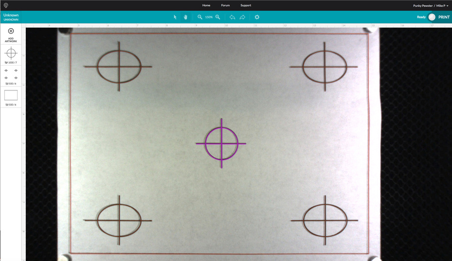
After-image once the laser was used to run the same exact pattern. While it’s true I could run this pattern 20 times without moving the target and it will hit the same spot every time, that does not help folks who are needing to do tight registration. The laser is not registered to the camera image.