And maybe a limit switch…
So how exactly would that work? I assume the built-in pattern would be engraved on a piece of waste material. Then what? The cameras read the position of the markings? The user gets out a ruler and types in dozens of offset values across the bed?
No, software in the cloud would find grid points in the image and compute the inverse map to place them on the corresponding points of the test pattern.
2 Likes
What reads the grid points? The lid camera?
1 Like
Yes it is the lens distortion of the grid camera that we want to correct.
OK, so they get an image of the engraved test pattern, with some unknown distortion across the bed. How do they trust where the camera says the pattern is? This is the crux of the problem. The camera is the unreliable element. Chicken and egg.
It is?
Run that same test and see what you get.
Yes. There is such an extreme angle of imaging with the super-wide-angle lens that no measurement in the lid camera image can be trusted. It has to be the head camera. It’s the only hope.
You can engrave a test pattern open loop that is as accurate as the motion system. For example an array of small crosses.
You can grab an image of that and locate where the grid points appear in the camera image.
By interpolating between the crosses you can make a transformation that maps all the camera pixels to the corresponding screen pixels where the preview of the pattern appears. You then have an accurate preview system to approximately pixel resolution.
That isn’t accurate enough for pass through and doubled sided etc, but it plenty accurate enough for manual placement, which is the problem discussed here.
3 Likes
CNC machines were capable of marking a consistent field of squares without the use of a camera for many years. It’s not chicken before the egg.
People are combobulating accurate motor control with image correction, and they’re two different steps.
1 Like
Ah, yes. I get it now. Thanks.
Nothing scares me more than a Happy Client turning into an Angry Client.
I seriously feel for you, i hope this is sorted soon before you hit the tipping point.
5 Likes
GF may have a little work to go but camera optics and image de-warping are predictable by physics and mathematics. I mean obviously someone else has done it. Industry has deemed that camera inspection systems are adequate for high speed inspection of parts in critical paths and they’re inspecting for tolerances in the thousandths and ten-thousands of an inch. I don’t imagine many of us are running into needs that tight.
2 Likes
Quick update. Only one little test today. Same image, same material, roughly the same spot on the bed (center)…
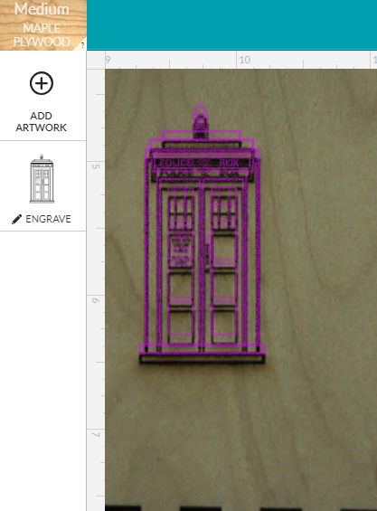
Tonight, as you can see, it’s almost perfectly aligned horizontally, but off vertically by a relatively small amount.
This week is really bad for me. Working 2 jobs, I’ll basically not be home this week (aside from a few sleeping hours here and there). So no time to reproduce this result until maybe tomorrow.
10 Likes
Heh. That’s me nearly every day.
1 Like
There’s a big difference between expensive industrial-quality imaging systems, which would never use super wide-angle viewpoints for critical inspections, and a mass-produced consumer product.
Yes, in a perfectly controlled environment, the math works to de-warp an image. But the wide-angle viewpoints introduce a sensitivity in the calculations that small variations in manufacturing wreak havoc upon. It’s like trusting the 10th digit on a calculator when the numbers being crunched have only 3-4 meaningful digits.
Blind reliance on “physics and mathematics” will only go so far in an environment like we have. Even the slightest warp in the material will throw all the calculations out the window without some thorough modeling of the surface characteristics.
4 Likes
I thoroughly understand the difference. My misconception was that I assumed there was a physical registration sheet that would be imaged first, not a built in registration pattern. That makes all the difference.
1 Like
Yes there is no way a fixed de-warp algorithm will work across machines. There has to be per machine calibration and we were led to believe they are factory calibrated. The bizarre thing is they are off in the centre where none of the wide angle or material thickness considerations apply. And @Tom_A’s machine seems to be off in one axis one day and the other axis the next day.
Since the camera can’t move by that amount I think the homing routine must have a large variance. That would explain why the full bed can’t be used because that would risk hitting the endstops.
It is very odd though that a camera looking straight down at a white on black logo can’t locate that very accurately and repeatably. I can’t think of any other reason why it would vary in the centre though.
An interesting experiment would be to engrave a cross in the middle multiple times, turning the machine off and on in between. Perhaps changing the room lighting. If the crosses move around on the material then the homing is not repeatable. If they are all on top of each other but they move in the camera image then the image is being offset randomly.
5 Likes
Also opening and closing the lid between experiments.