I load my proof grade material to the back left corner. Originally, the camera would show the entire size of the material, but recently, it is cutting off the top inch or so in the camera preview when I place my image. I have been placing my material in the front right corner to compensate for this. I have tried calibrating the camera per the link glowforge supplied, but I am confuse as to why the camera shifted and the back left corner orientation doesn’t show correctly anymore. I designed a calibration cut and score which works correctly at the front right corner placement, but I am losing the top 1.5" or so of material for use, either placement location. Thoughts?
Your material should be loaded to the front right corner for fullest material use. The Glowforge operating area is smaller than Proofgrade sizes, so you will always have a little margin that isn’t used. You can adjust for this by moving the material a little, but I find it is good to have a little margin to keep things stable and to help prevent fires in the event your design gets a little too close to the edge, since thin areas are much more likely to catch fire.
6 Likes
You are not really losing anything as the usable area has always been approximately 10.9" x 19.5". The camera shows the usable area. Looking at your printhead in the home position you see that it cannot print behind itself. That 1" of the board can only be accessed by rotating the board after you have used it for cutting something else.
3 Likes
Don’t worry, your camera hasn’t shifted. As @ben1 says you need to load to the front right. The back left has never been in camera view or available.
3 Likes
Really? Then why can I not see the the entire surface of the material that I place in the Glowforge? Until recently, I could see the entire sheet.
1 Like
I understand, but I cannot see the entire surface of the material loaded into the Glowforge. Previously I could see the entire sheet and edges of the full proof grade material.
1 Like
I can see why you felt like you could, but I guarantee you that a normal GF has never been able to see the entire 12x20 sheet of material. There’s always a bit along the top and left that is out of view of the camera. It trips up almost everyone starting out.
4 Likes
True enough. But if you had it zoomed out a step or two, you’d see the piece of material with a lot of black borders that if you weren’t looking closely at the ruler guides might make you think you were seeing the whole thing. Then the first time it showed at regular zoom levels you might not see the black borders anymore and think you weren’t seeing the whole bed anymore. Guess it depends on the OP’s monitor size & zoom levels.
1 Like
This is also true
To all those that replied,
I appreciate the responses, but the image I see on the screen is of true size, 100%. I have zoomed in and out to check if that was problem, but it is not. I took a blank piece of proof grade material, marked all 4 sides with a scale of 2”, marking every 1/8”. No matter where I place the material, the front edge and right side show markings of correct length to the edge of the material. If I place the material in the back left corner of the tray, the left side is missing 7/8” of the image and the back side is missing 1 5/8” of the image. Not a pattern, but just the image of the material. If I disregard the edges of the crumb tray, I can align the material so that all edges are visible, but this puts material outside of the cutting area of the head. As I mentioned before, it appears as though the camera is not centered properly in the lid. The image is cut off at the top, no black borders if I were to zoom out. jamesdhatch is correct in his statement, I was able to zoom out before and see the black borders around the outside of my material, but now I cannot.
1 Like
I’m sorry but the entire proof grade board has never been visible in the laser bed. You can see how it tucks under the laser arm - which means it can’t be reached by the laser.
1 Like
Jeffreyp, I understand what you are saying, but when I first bought my glowforge I could see the entire size of the proof grade material in the camera image. I also understand there are limits to how far the laser head can cut to the edge, but when I am losing over 1.5" of image, sl ethi g is wrong with the image the camera is showing. If I move my proof gr8 rade magerial so far off the edge of the xrumb tray, I can see all edges of the material in the camera image.
I don’t know how many of us need to chime in but no, the entire sheet of proof grade would not have been visible. I’m sorry.
1 Like
Perhaps your case may be better made with pictures showing what you can see so that we can also see it? There may be something that we are missing or there may be something that is different about how you are looking at it so we can see more accurately what you are referring to.
1 Like
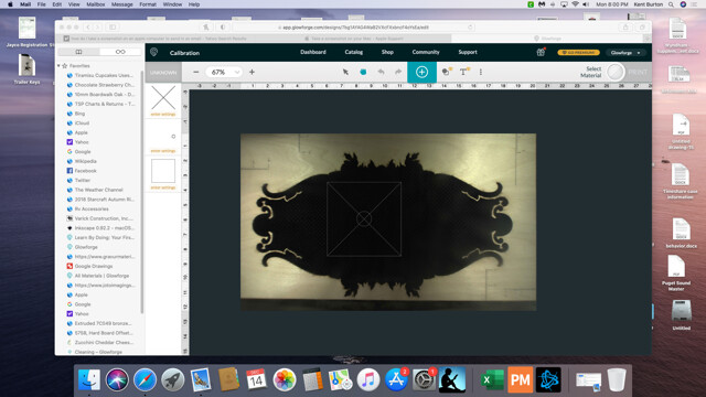
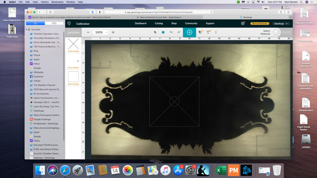
I am not trying to be difficult, just understand. I know I was able to see the entire size of the proof grade material when I initially purchased and used my glowforge. I have attached a few screen shots of the image of a full size of material. It actually measured out to be 11.750” x 19.750”. I drew in a scale marked off in 1/8” increments to show what I am talking about. The material is placed in the front right corner of the crumb tray and I lost 1/8” on the left side, no big deal, but I lost 3/4” of the image on the back side of the Glowforge bed/crumb tray. As you can see, I am not interfered with scale of the screen, but please note the greyed out portion of the 67% image. I can see the front lip of the crumb tray. I could move the material towards the front of the crumb tray and capture that missing distance in the image, but I believe the camera is not centered or aligned with the machine.
P.S. this is not the owner of the forum, but her husband. If you think I ambling difficult, it is me and she is just a sweet kind peach of a person
 should not be directed at her
I moved my material off the crumb tray to completely capture the left and back side material. If you look at the image, Glowforge will allow me to cut/score the material, even though it is clearly off the material. The camera image must set the limits of the acceptable cut parameters as long as the pattern is within the camera view. This has to be a mistake or misalignment of the camera. I am very open to the possibility that maybe the camera shifted if it was hit while loading the material to be cut.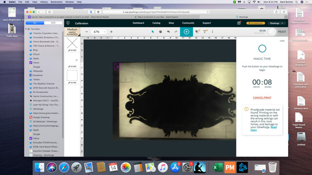
another image where the cut is clearly off the material, but Glowforge is allowing me to process the image.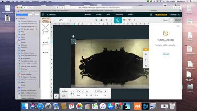
The camera is mounted on the lid. It doesn’t get bumped by material. It is fixed and shows a very clear image of your bed. I believe you are mis remembering what you saw a year ago. Your usable area is within the specs of the Glowforge so I just don’t know what you consider the problem. With precision placement you can see exactly where your cut is going to be within the 10.9" x 19.5" usable area. As for placing your design off of the material, the Glowforge limits placement to the usable area. It doesn’t care if you have material there or not. The upper left limit position .562 X and .522 Y axis is exactly what my machine shows. If your cuts are where you expect them to be, and if you can access the full usable area, then it is really hard to grasp what the issue is except that you can’t view the top of the board which you can’t use anyway.
1 Like
The view from the camera has always been what it is. From all the way back in the olden days of yore, the lid cameras are not set to show the entire bed area. Never have. It’s not a thing.
1 Like
Everything you have shown here is exactly the way the interface has looked since I started working with my Glowforge over two years ago. I think that you have either misremembered or misunderstood what you were looking at.
What I do see is that in the first images you have not selected an operation. In the later image you have selected the operation. Once you select the operation, the GF calculates the additional restricted area due to the acceleration requirements for the print head. This is the gray mask that comes up. The acceleration profiles have changed from time to time and the gray mask areas will change accordingly.
1 Like