Can you help me make dimensioned drawings in Illustrator?

Hello everyone,

Quick question, does anyone use (or know how to use) Adobe Illustrator to make “dimensioned” CAD drawings to make awesome things on a Glowforge?

I used to use Fusion 360 and had great success with it, but unfortunately the latest version Autodesk pushed out no longer runs on my current OS. I am still running OS X El Capitan (Version 10.11.6) because of my MacBook Pro (13-inch, Mid 2009) will no longer upgrade to any more recent Mac OSes.

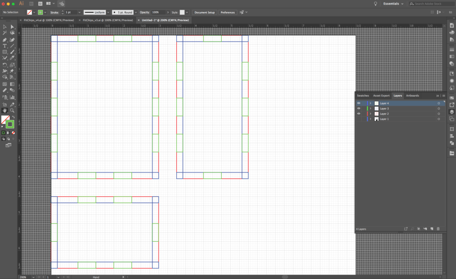
I do have Adobe Illustrator CC, and I’m decent at making vector drawings and illustrations, but I am not very familiar with an easy way to input dimensions for complex objects or 3D designs.

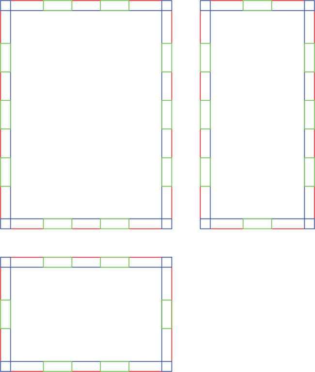
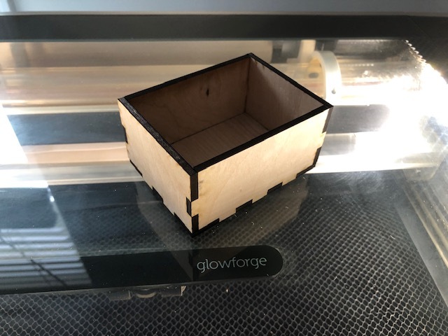
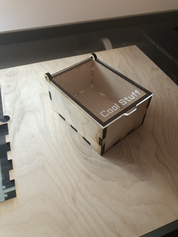
For example, let’s say I wanted to make a simple box with finger joints. Like the one I made a few years ago… Small Box and Lid with SVGs

In Fusion360 I could define my material thickness, define the depth and width of each tooth, export it and no problem.

However, working in illustrator, I can draw a rough outline of what I want my box pieces to look like, but I don’t know how to go in and select each individual line and input a dimension.

I can select a path with the Measure tool or the Document Info tool, but it only tells me the dimension. How do I select and then input/change the dimension?

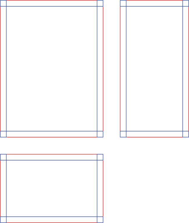
The only thing I can think of as a way to get around it is to insert an object (like a rectangle) with the dimensions of the material, turn that object into a guide (or create guides from that object) and then draw the box pieces from those guides.

This will work, but then let’s say you want to change your material thickness, you would have to go back and create new guides and move the object’s lines to match those new guides. A lot of work. It would be great to just be able to select the paths you want to change, type in a new dimension, press enter…

Make sense? Thoughts/Ideas?

(If you want to contribute so I one day I can buy a new laptop, please consider getting one of my Glowforge covers on my Etsy page: https://www.etsy.com/shop/spaceforactivities/)

1 Like

Ok, I just made an example the “long way” I described above…

(Material thickness of .175")

Step 1: Made box shape outlines. 2" x 3" x 4"

Step 2: Made .175" guides for material thickness.

Step 3: Made .5" teeth for the finger joints.

Step 4: Use Shapebuilder tool to combine the shapes into complete pieces.

Step 5: Duplicate sides, prep for export as svg…

What it looks like in illustrator…

Your only concern would be to compensate for kerf.

I create interlocking tabbed faces manually (in Inkscape). What I do is make one tab section then duplicate and move to the next position. I can create “mating” notches or holes with the correct kerf adjustment, and replicate them together as I move across mating edges.

There are many automated to ways to create “boxes” but I prefer variable spacing/width and rarely make boxes anyway. More for joining panels on unusual shapes.

2 Likes

eflyguy, thanks for the reply.

Creating a box was just a simple example, I’m really interested in understanding what my options are to go back into Illustrator and make tweaks after the fact (for kerf, or clearance issues).

Thanks for sharing your workflow, to account for kerf do you use an “offset path” or “outline path” to make adjustments? How often do you have to go back and tweak it, or do you have a quick reference table of kerfs for your various materials and can get it on the first try?

Test box came out pretty good…
IMG_1832

1 Like

I enter dimensions manually, I effectively use 0 path/stroke width. I have cut sample pieces of common materials I use, and I tend to use whole numbers for tabs, so I just kerf compensate (under-size) the slots/notches. I just look at the numbers and adjust my desired width by the decimal amount.

2 Likes

I have the same issue, which is why I tend to do even the simplest things in CAD. Illustrator is an art program, and the only techniques for getting accurate mechanical drawings are the hacks you have described. I very quickly grow frustrated not having constraints and parameters.

4 Likes

But Illustrator would be perfect with just that one teeny tiny (major) change, wouldn’t it?

I think then it would be called AutoCAD. :slight_smile:

4 Likes

Hahah. Very true.

What you’re asking to do in AI is pretty easy.
I think you’ll enjoy getting to know the Illustrator Transform panel :slight_smile:
It’s the easiest way to resize and move objects numerically.

https://helpx.adobe.com/illustrator/using/transforming-objects.html

When you’re good with that get to know the Direct Selection Tool (white arrow vs the black arrow) it’s fairly easy, for example, to select all the vertical line segments in an area and then move them with Transform palette for kerf adjustments.

https://helpx.adobe.com/illustrator/using/editing-paths.html

(Btw, The shortcut way to get to Transform is to select whatever you need to move/resize, hit letter “v” on your keyboard and then hit “enter”, a mini transform box will pop up that you can enter numbers into, this works for partial selections with the white arrow as well as full objects)

1 Like

It may be an art program, but AI is more than capable of precision quite easily. It’s just a matter of workflow and familiarity with tools. Constraints and parameters would be nice tho.

(Similar complaints are often made about Sketchup)

1 Like

I don’t think anyone said that Illustrator isn’t capable of precision. I use Illustrator all the time and I find it very useful for certain things. It’s just not built around the right paradigm to do mechanical drawings. You can get things into place with a series of aligns and transforms. But there’s a big difference between that and being able to specify the dimensions or position of an object in terms of other objects and have it stick. It’s the process of repeating all of the movements to get to a desired state that I find frustrating, and that sends me to Fusion 360 whenever I have to design something.

4 Likes

Illustrator is awesome but what I wouldn’t give for parametric design - if there’s a way I don’t know how to do it please tell me. I hate the work-flow out of Fusion.

2 Likes

No true parametric capabilities as one is used to in CAD ASFAIK but there are various techniques using symbols and/or effects that can emulate some of that functionality (depending on what you’re trying to do).

Side note: there’s an expensive plugin called CADtools that’s useful for adding dimensions, setting line weights and drawing in scale among other things.

1 Like

Thank you, I’ll check that out. Symbols is a good idea, be useful for common size notches and things. thanks!

Also if you want to adjust notches - just change the symbol :smiley:

1 Like

Have to agree with @chris1 in this discussion everyone. And that is coming from someone who has composed printed bulletin documents in Excel.
Can’t beat a parametric CAD program for this type of work.

One could use clones in Inkscape but I am not sure it is worth the extra effort.

With a bit of google-fu- there is this…

Thanks for everyone’s feedback.

I’ll keep playing with AI. Thank you for the tip about “transform” that has been a rarely opened window up until this point.

Just to close things out… Here is what I made.

4 Likes