Here is a great article about CO2 Laser cooling:
Controlled cooling
11/01/2006
Stabilized cooling is key for CO2 laser processes
Frank Domnick
The carbon dioxide laser outputs instable energy due to many factors. Cooling contact to the generated heat is fraught with complications. Because of its nature, high-power metal cutting and welding do not require the level of energy stability typically associated with non-metallic processing where, for example, in the kiss-cutting of digital label stock a power variation of two or three percent may be the difference between not separating the article from the carrier, to piercing the carrier face enough to cause catastrophic web tears on process machinery.
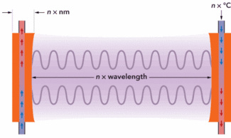
FIGURE 1. Power and wavelength instability caused by changes in cavity length.
CO2 laser cooling affects not only overall power stability, but also maximum power output achievable, wavelength, and beam pointing stability. Depending upon the integrated optical delivery component set-up, it may also have further effects not directly related to the laser source.
The majority of non-metallic processing applications have traditionally been performed using sealed waveguide CO2 lasers, where only the mirrors at each end of the cavity can be cooled by contact with water flowing through channels bored as close as possible behind the reflective surfaces, or sealed slab CO2 lasers, where in addition to the mirrors, heat can also be extracted from the water-cooled electrodes. When the mirror blocks then expand and contract due to thermal instability, the distance between the reflective surfaces change, and usually by no more than a distance of a few nanometers.
Because the power and wavelength of the laser are determined by the multiples of waves between the reflective surfaces, and because only very small expansion and contraction movements of the cavity mirror blocks will occur with temperature change, it is therefore easy to see how, for example, a 50cm CO2 cavity, lasing at 10,590 nm can alter when the distance between the reflective surfaces needs only to shift by 0.2 µm before the laser cannot maintain the P20 transition line and ‘hops’ to a combination of both P22 and P16. A further shift of 0.3 µm will push this to P24. These additional transition lines do not produce as great a power output, and are the main area where instabilities occur. This explains why longer resonators may produce greater stability. Furthermore, the absorption spectra of the target material will show greater processing instabilities, where a thermally active power meter will not read changes in wavelength.
CO2 laser manufacturers typically stipulate a power stability figure within the technical specifications from a cold start, when equilibrium may be reached after a period of 15 to 30 minutes. However, most processing techniques will require laser output for considerably shorter than a few seconds. Therefore, the time between process repeats may also have an effect on stability during the period where the cavity mirrors cool. One can see that fast response to thermal changes becomes important when a higher level of process stability is required.
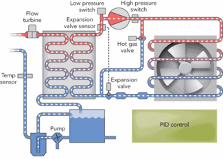
FIGURE 2. Typical air-to-water chiller circuit PID control elements.
In regard to the laser itself, if water cooling is being used, and the power level is high enough, it is wise to extend the circuit to cool the fittings of beam delivery optics that may also be affected by other parameters, such as thermal lensing. Furthermore, galvo motors also benefit from thermal stability, especially under high heat loads, so it can be wise to extend the cooling circuit to pass through the motor retaining blocks.
Modern high-end laser chillers employ a feedback loop in the form of a PID (Proportional-Integral-Derivative) controller to regulate cooling water temperatures. A sensor measures water temperature to give the level of difference or ‘error’ from the required norm or ‘setpoint,’ and then the intelligent controller calculates the difference before sending fine adjustments to the hot-gas bypass valve to ensure ±0.1˚C temperature control.
The PID loop calculates error in three separate ways: Proportional (cancelling out the current error directly), Integral (measuring time the error has continued uncorrected), and Derivative (predicting future error from the historic rate of change of the error over time).
The speed at which the PID loop performs its functions is key, as this determines the entry cooling water temperature to the laser. The measurement, calculation, and adjustment cycle can be controlled by programming to function at many times per second. Naturally, the length of the cooling circuit, and the distance and speed the cooling water travels, also has an important part to play.
Even the temperature and type of water make a difference. Recent studies suggest that de-ionized water is aggressive to both metal and plastic fittings, causing wear of the cooling ways and adding particles that will clog filters and alter the cooling circuit over time. Regular supermarket sourced still drinking water is proving to be far gentler on these fittings.
Algae inhibiting agents are corrosive and also create wear. Merely increasing cooling capacity, decreasing operating temperatures to 18˚C (65˚F), and using light-fast hosing eliminates the requirement to use these agents.
Issues may also arise with dew point, which is easily controlled by using a Nitrogen purge gas, as commonly recommended by the laser manufacturers. Modern swing-pressure absorption Nitrogen generators are cheaper, smaller, and quieter than compressor/clean air filter equipment, with very low vibration levels. The small size of the Nitrogen generator means that it can be incorporated into the chiller housing, and has the same six-monthly service regime. Cleanliness of delivery optics also remains paramount to system longevity and stable processing.
In applications where stability is critical, the ambient temperature of the system location and the laser system chiller become the first factors in a chain that will have a bearing upon processing. Instable ambient temperature of more than ±2.5 percent will affect chiller performance, depending on chiller cooling capacity.

FIGURE 3. Random banding effect on doped BoRaGlas raster scanning process (upper), cured by changing chiller and programming PID control to suit (lower).
BoRaGlas GmbH (Halle, Germany), a processing company, highlights the problem of cooling instability with such clarity that a simple solution could be met by a change of chiller type and re-programming the PID loop. They are specialists in the scan marking of a doped surface on glass using CO2 laser wavelengths. A 25W Synrad laser emits a constant output at 5 kHz, 95 percent duty cycle that then passes through an optical power stabilization system, to be modulated via an acousto-optical modulator. The normal stability of the Synrad 48-2 laser after a 20-minute warm-up reaches <±3.6 percent. The optical power stabilization system then improves this stability to <±0.5 percent.
In calibration testing it was highly visible that a mysterious banding was occurring randomly during raster scanning of the target. Observing the process over several hours, it became evident that the darker banding occurred at the same time as the chiller’s compressor cut in and out. The decision was made for the chiller supplier, Termotek AG (Rastatt, Germany), to overnight ship a replacement chiller with fast ±0.1˚C PID control. On installation the following morning, Termotek’s technical staff advised the customer on experimentation with a variety of PID programs until the perfect match was found to eliminate the banding problem of the target process.
And so it remains that one of the prime requirements of any end-customer will always be an accurate, repeatable process. Without balanced, controlled cooling, no other energy transmission parameter of an integrated CO2 laser system can be held stable.
Frank Domnick (CEO) is with Termotek USA, LLC, Santa Clara, CA. Contact him at info@termotek-usa.com.
src: http://www.industrial-lasers.com/articles/print/volume-21/issue-11/features/technology-report/controlled-cooling.html
