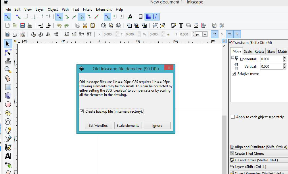
I’m not sure what your solution is going to be, but I think I can explain the problem…
Shapes in SVG are usually specified using unit-less coordinates. As has been mention already, different programs use different default sizes for these coordinates such as 1/72, 1/90, and 1/92 inch.
In order to set an actual size based on real-world units SVG uses a combination of the viewBox, width, and height attributes you’ll usually see near the top of the file.
The viewBox specifies four numbers which determine the coordinate system used in the drawing. The first two numbers are the x and y coordinates of the top-left corner and the second two numbers are the width and the height of the overall drawing area. The numbers are using the same unit-less coordinate system as the actual drawing.
The width and height attributes specify how big you want the drawing area to actually be and this can be specified using real-world units (mm in this case). In order to render (or cut) the drawing at the correct size, all of the coordinates in the drawing are scaled based on the ratio of the size of the viewBox and the size indicated by the width and height attributes.
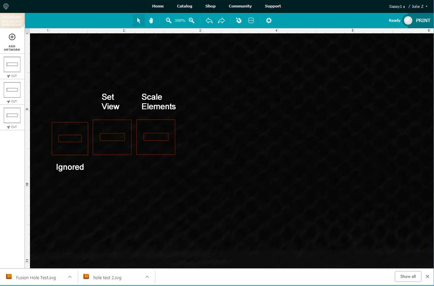
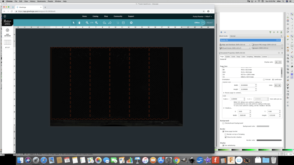
In this case, both files have a width and height specified, but only File 2 has a viewBox. Without a viewBox, the correct scale factor can’t be determined so assumptions need to be made and one of 1/72, 1/90, or 1/92 inch will usually be used. If the program drawing (or cutting) uses a different scale than the program that made the file, you wind up with the wrong size.
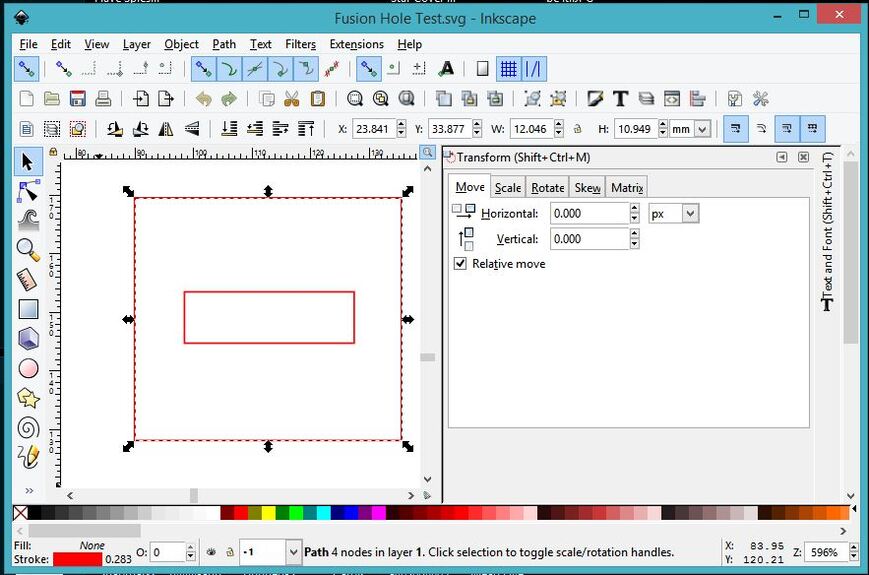
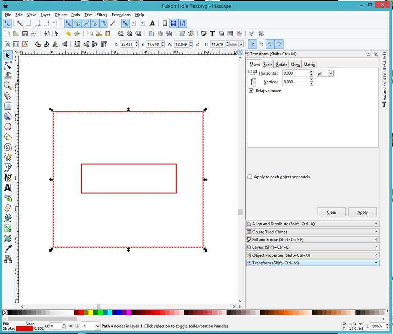
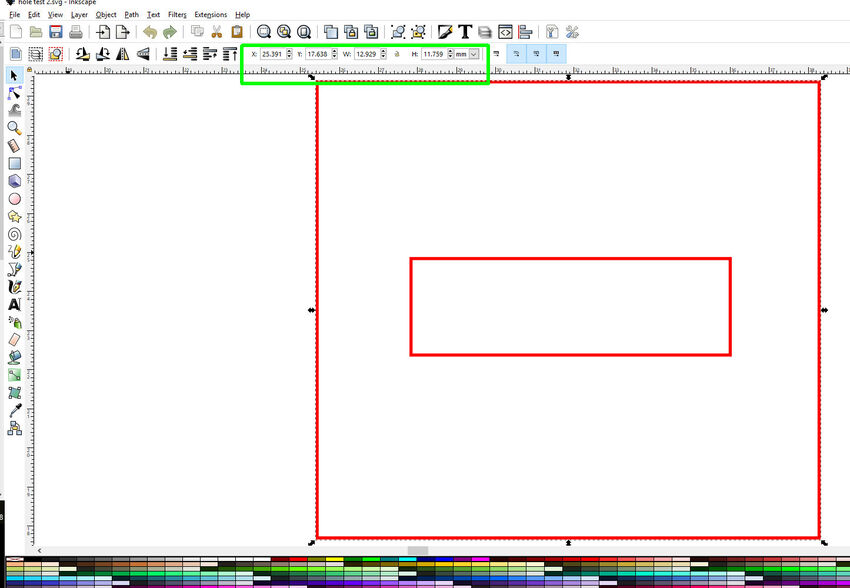
In the file “hole test 2”, I see that the width and height attributes match the width and height in the viewBox. That means that all of the coordinates are in mm. It’s possible that adding a viewBox=“0 0 454.66 276.85999” to “Fusion Hole Test” (right below the height= line) will fix its size, but only if it is using mm as well.
Hope this helps!
 Great description. I’m going to study it.