A higher percentage of Lar’s stuff is CAM oreanted but he covers a lot of the same stuff you and Tyler cover as well. I find it fastinating how I can watch three diferent people working for the same company and get something new from each.
1 Like
@Secret_Sauce, are you planning on covering how to create a living hinge in Fusion 360? I’ve gotten stuck as the lines I draw in the sketch don’t have any effect on the extrusion. I could just export the sketch but I added finger joints in 3d mode, so my sketch isn’t completely up to date. I was going to go back and do the finger joints in sketch mode, but if you’re going to cover this, I may just wait :-).
Cole,
I wasn’t planning on showing finger joints, but maybe I should!
I still have some room in webinar 06, so maybe I’ll add that to the agenda.
In the meantime, please send me your Fusion 360 file and I’ll tell you how to fix it.
Send it to my Autodesk email address.
Jason
1 Like
“Open” or single sketch lines will not extrude in a solid. You would have to draw those lines as closed shapes in order for them to update into the 3D model.
Makes sense. But then how does one design for a single vector cut line in fusion 360?
1 Like
You can export sketches to DXF files, and that will also allow single/Open lines to export.
2 Likes
I’m aware of that, but I’d like to export the face of the 3d model since I have made changes in 3d that aren’t reflected in the sketch. Being limited to the sketch mode also seems to remove some of the cool stuff about fusion 360. Not trying to be difficult, just still trying to wrap my head around how fusion 360 is intended to be used
1 Like
If you can give/show an example maybe one of us can help. The resson F360 won’t extrude anything that is not a loop of some type is that if it did the extruded body would not be “air tight”. This goes for Sketchup and any other 3d modeling SW as well I guess.
F360 works quite well this way. Sketchup, you can break a model and have some realy weird things going on almost like it exists in 4 or 5 dimentions!
1 Like
Here’s the 3d view of the model:
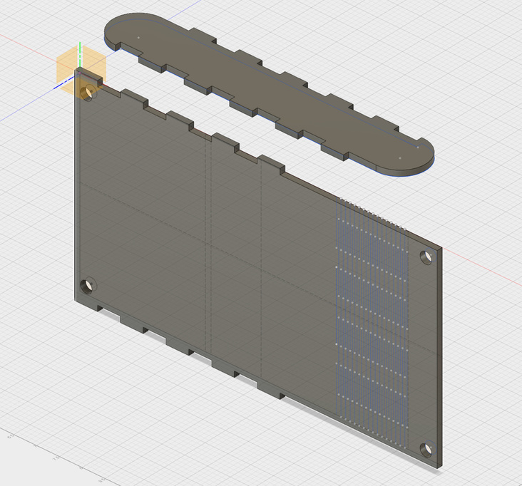
Here’s the sketch:
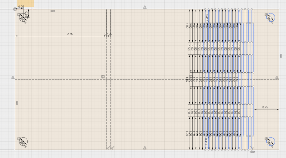
I added the finger joints in 3d mode, so they are not in the sketch. I did the hinge in the sketch, but it uses open paths so doesn’t effect the 3d extruded object. The I understand the what and the why, but I’m still unclear on how to actually design a hinge without being stuck in 2D mode.
2 Likes
I’m in uncharted waters here so take this for what it is worth.
If I was trying to do this I’d try to combine this sketch with the one you would get from projecting after adding the additional geometry.
Or, you could include the finger joints in the original sketch. Yes, I like to just lay down a linear array of lines and extrude the joints but a lot of people do that in the original sketch.
1 Like
Mark and Cole,
Indeed you cannot extrude an open sketch as a solid. Fusion 360 does not yet have a “thin-cut” feature. You can extrude an open sketch as a surface, but I don’t think that will help you in this case either.
In short, I recommend designing everything the way you have been going so far. However, I wouldn’t try to use the living hinge sketch to alter the 3D part. Meaning, I wouldn’t use the sketch to visualize in 3D what the part will look like with the living hinge cut through it.
Instead, I would do exactly what Mark suggested and project geometry.
When your design is complete, create a new sketch and use “project” to project all of the edges of the 3D shape into your sketch. Then, I would do the same for the living hinge sketch entities. Result: one sketch that has the outer profile plus the living hinge. Then, export that sketch as an SVG using the Shaper Utilities add-on OR export as a DXF by right clicking on the sketch in the sketch folder. Either way, bring the file into Illustrator or Inkscape to separate cuts from scores from rasters before sending to the Glowforge UI.
I know this isn’t perfect. Remember that each software has its limitations. Using Fusion WITH Illustrator or Inkscape is the best choice.
Just my quick thoughts without having designed any living hinges myself yet.
-Jason
5 Likes
Oh, and @Cole, there is a new sheet metal module that while called sheet metal, it is ideal for bending boards around to model them with living hinges.
2 Likes
@Cole, gotcha! The screenshots helped a lot. Like @markevans36301 and @Secret_Sauce said, you can create a sketch of the whole thing and use the Project command to bring everything into one sketch.
If you want to visualize the living hinge in the model, and mind you this is for visualization only and not the final production “tool path”, you can extrude the open lines in the Patch workspace, which will make them into surfaces, then you can add thickness to them to make into a solid body, also in the Patch workspace, and also a parametric feature. You can then Cut the “hinge” solid from the model.
Now doing this so it shows up in 3D is the tricky part, you might be able to use the sheetmetal workspace and fuss around with bend radius settings enough to get it to show up right. Then you would need to add a flattened view of the part so you can cut out the living hinge section in the proper place more easily. Not sure how comfortable you are with the sheetmetal features. I have not done this personally but I’ve kicked around with it a bit to make patterns for boxes and I’m sure you can figure out how to visualize a living hinge this way too. It just won’t translate into a laser cuttable file the way you’d like because it will be a completely closed shape cutout instead of open tool paths.
2 Likes
The CAM/Glowforge post processor method of creating SVGs from Fusion 360 can (likely) be used to make a single SVG that includes outlines from both the modified 3D geometry and the living hinge geometry. This method takes a some extra work and introduces some problems of its own. It also gives you the option of kerf correction, so that’s nice. But if combining sketches doesn’t appeal to you, I think it can be done. I can record a lil’ video of me trying to do it if you want. (It’ll prolly be a rough video since it’s not something I do regularly.)
Biggest problems, as I see it…
- The SVG will be a collection of lines that happen to share endpoints sometimes instead of a collection of closed shapes. Last I heard, Glowforge doesn’t combine lines that share endpoints, so the SVG, if left unmodified, will cause the Glowforge to bounce around the design cutting the individual lines one at a time.
- Extra work. Doing this requires going into the CAM environment, which most people would prolly like to avoid, if possible. It’s not exceedingly difficult or anything, but it has its own quirks and stuff that need to be learned.
Jason…thank you so much. it will be exactly what i personally need
Sorry folks, one more question that seems like it should be obvious to me. How do I project form one sketch to another. If I press p and select the lines from sketch one, when I press ok, they seem to be projected onto sketch 1 still. How do I get them to project onto sketch 27 (which I just created from projecting the body)?
1 Like
I’m not going to give a specific answer as a) I am but an amateur myself, and b) without seeing exactly what you are trying to do I’d most likely lead you down a blind alley.
So, instead, let me tell you how you can help yourself.
Every command that had a dialog box has the additional info right there without having to open full-blown help. just click the (i) at the bottom. If that is enough, great, if not, there is a button for even more help.
Anything that doesn’t have a dialog box, just type it into the help box at the upper right.
Also, two more things. Copy past works for a lot of things in F360, it is easy to forget this, I know I do. Finally, one of the best ways to learn is to simply open another window and experiment! You aren’t going to break anything so experiment away.
1 Like
Thanks Mark. I was going to try to copy paste but was concerned about getting the alignment off.
The nuance was an order of operations. I wanted to select the things to project first but that made my active sketch the one that the lines were already on. I had to start from the target sketch and then click each line individually after pressing ‘p’ to project.
I should also mention, this was after “experimenting” for a while and continually getting stuck on the same step. I know it seems like it, but yall are not my first line of trouble shooting.
1 Like
Legit concern but I have not found a limit to how far I can zoom in yet! And by selectively controlling what you snap to you can get alignments perfect.
I hope I didn’t come off as not wanting to help, I do, just didn’t have a clear enough picture of what you were trying to do.
I get very stuck myself sometimes and I hope you’ll get good somewhere that I’m not so you can help me out.
Thanks for the videos! I’m trying to catch up on them. I had to get out my translator when you mentioned Power and Speed instead of Pews and Zooms. 
2 Likes