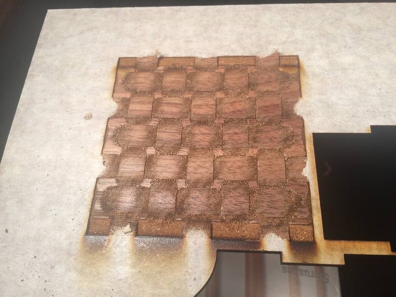
Took the time to do @marmil’s weave in Proofgrade walnut ply.
This first is 100% power, max speed and 450 lpi.
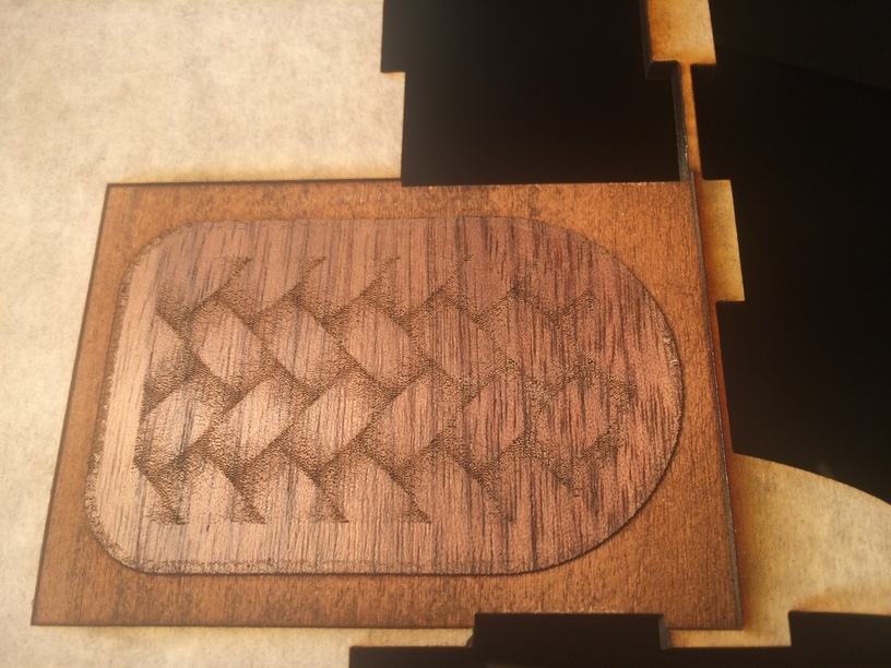
The second is max power, speed and 340 lpi. The darker walnut would require some tweaking of the design for contrast.
I can imagine the second tiling to make a nice picture frame pattern.