So I quickly searched the forums, and didn’t see this asked and answered anywhere…
BIG WARNING - IN NO POSSIBLE WAY DO I RECOMMEND PEOPLE ARBITRARILY DO THIS. DOING SO WOULD BE VERY DANGEROUS. I’m just trying to find references in the public eye to know whether it has conceptually been attempted.
Given that laser cutters have a limited thickness of material, and that some objects might consist of short sides you’re trying to engrave…
Has anyone heard of someone taking something super reflective – say, an old hard drive platter – and propping it at 45° so-as to reflect a downward beam towards the rear… and engraved on the front-side or an object laying flat?
Technically you can; but, as @jrnelson stated, the optics aren’t designed for it. You will still be limited by the focal length. So the distance from the head to the mirror + the mirror to the material has to be equal to the focal length.
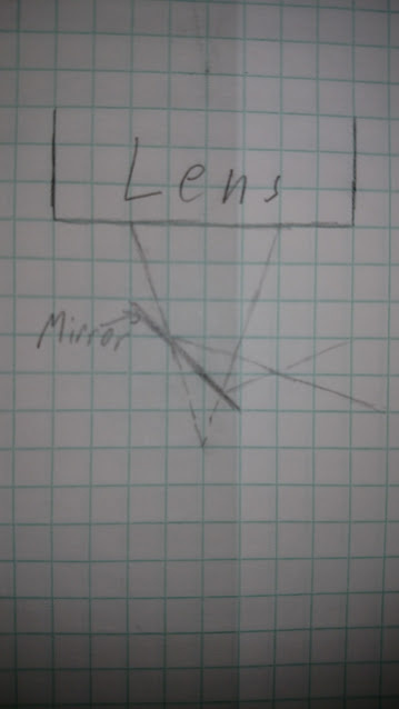
Rough drawing, didn’t have time to find a protractor.
Okay, but focal length can be reduced by placing the mirror butt up against the material, and the focal length moved closer (head down, towards the mirror).
It can be done, but can anyone cite public records of doing it?
From your sketch (and consideration of the physics) it look like you want a flat as close to the output lens as possible. Everything still focuses. Does the focus point clear the head going sideways?
Possibly a longer focal length lense and if mirror is not at 45 you could do some translation to have distance from mirror give some “z” changes…but not trivial as that will move focus point as well. Nonlinear, dynamically adjustable mirror
I’m not an engineer, physicist, eye doctor, lawyer, insurance adjuster, nor reality TV show host; but I’ll share my thought anyway: That sounds like a TERRIBLE idea.
A major issue you would face is getting the proper curvature of your mirror. You are still trying to get a focal point for proper energy concentration, which means you want to have the mirror before the focal point, while the beam still has a measurable width.
But, the beam is conical, and in order to reflect it 90 degrees, you need a mirror at 45 degrees, which means the raised portion of the mirror will encounter the beam before the lower portion of the mirror. Those two portions will not reflect in quite the same manner, because the angle of incidence is different.
You will still focus at some point… but I am pretty sure it won’t be where you would ‘expect’ the focus to be by just bending the light path at a right angle where the mirror is centered. I would have to draw out ray diagrams with a compass to be absolutely certain on that one.
I think at 45 degrees it all works out. The distance you lose before the mirror matches the distance you gain after it, and v.v. so the focal point is at the focal distance and reflected beam center. But I could be wrong.
Ideally you’d like a somewhat longer focal point, which would mean a slightly convex mirror, but I blench at getting that figure out and aligned.
i think the real problem with the 45 degree mirror is how you’re going to design a file to cut anything. How’s that going to work. Your focal length will only be correct for a single line across the face at a fixed height on the mirror. assuming you take a long mirror and put it along the x axis to give you the most working space, if you line the head up dead center of the mirror in x and y and use that as your ducks in the face of the piece, any change in x will keep the same focus and cut. If you move towards the piece in the y the cut will get lower in the z plane and the focus point will be deeper in the work piece. Moving away will make the cut point higher in z and farther from the piece. So you’ll be able to cut a nice pretty line. Your entire design file from Inkscape would have to be just a single line of a dozen different colors that you play out in different steps hoping you get the right order as you step through the angular rotation of the piece. Whew was that even English? Does that make sense?
I knew what you were talking about so I got to skip the names of the axes and stuff, but it makes sense. If the mirror is on the bed, Y axis movement will translate to height changes.
If the mirror is attached to the head, Y axis movement will translate to moving the focal point.
The Y movement will basically have to be taken out of the equation for it to work. It doesn’t look like the autofocus is in-line with the center of the lens, so that would be thrown out of whack.
The cone would be unaffected by the mirror, regardless of what angle it’s at (well, so long as the cone actually hits the mirror). (Sorry )
I had been assuming that people were talking about something like that various side-firing rotary bits that there have been threads about. absolutely if you were trying to do a flat surface aligned the other way it would get weird very fast. (You might still be able to do something, but it would probably require a coordinated movement in Y and Z)