My method actually focuses on creating the holes, not the fingers. It requires that you kind of think of the process inside-out, but it’s the only way I could create finger joints that actually work.
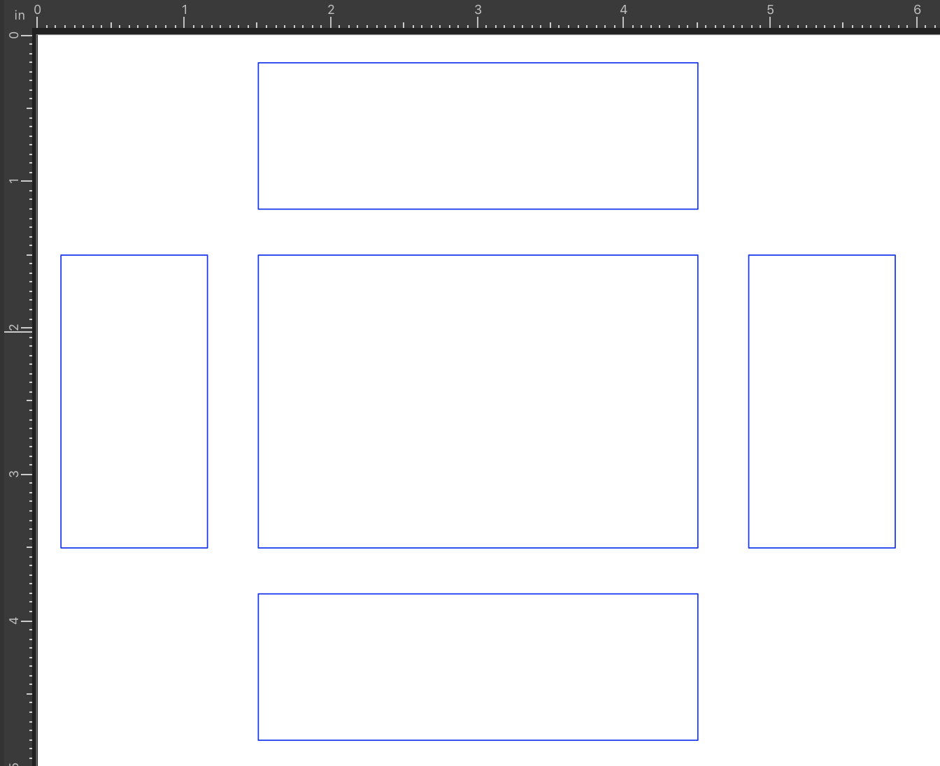
This is the sequence of steps for creating finger joints along one corner of a small box.
Sometimes it can be a little difficult to visualize how three rows of finger joints will fit together at a corner. This is what Amazon boxes are for – cut out some trial parts and put them together to make sure you haven’t made any mistakes, before you cut your actual material!
Note: for each of the steps below, click the triangle to see full details.
1. Create your box (or whatever) design using rectangles.
For this example, I’m just creating a small open-top box, 2" x 3" x 1".
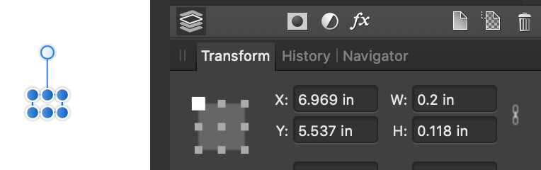
2. Decide how wide (approximately) you want your fingers to be, and make a rectangle with **width = desired width** and **height = thickness of your material**.
I’m using 1/8 in Baltic birch, so my height is 0.118 in. I like thinner “fingers,” so I’m selecting 0.2 in as my width.
3. Make a row of these rectangles to check for fit.
- Select this rectangle and use CTRL J (or command J) to make a copy.
- Move the copy over by the width of the rectangle by adding its width to the X-coordinate (see step 9 for screenshots).
- Give the copy a fill, to make it look different from the original rectangle.
- Now select both of them and duplicate, then move by adding double the width of one rectangle to the x-coordinate.
- Continue hitting CTRL J until you have a line of rectangles a bit longer than the longest dimension of your design object.
- Now you can move this strip against each of the edges of your parts to see where the fingers and holes will end up on your piece. If desired, stretch or shrink the row of rectangles to make any changes you want.
- When you’re satisfied with the fit, delete all but the original rectangle.
- Make a note of the new rectangle width – this will be your new spacing to use in step 9.
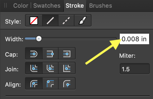
4. Set this rectangle's line width to the width of the kerf for your material.
I’ve found that 0.008" works pretty well for me, for 1/8" BB. Note that AD lets you input your measurement in whatever units you prefer, and converts it to points for you:
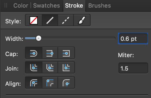
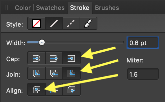
5. Check your settings for line ends (square) and join type (mitered), or things will get wonky in the next step!
You want to use square caps, miter joins, and align stroke to center.
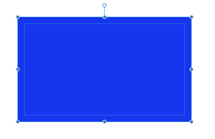
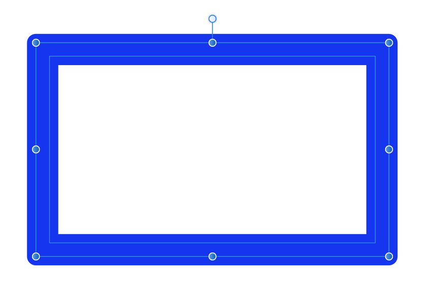
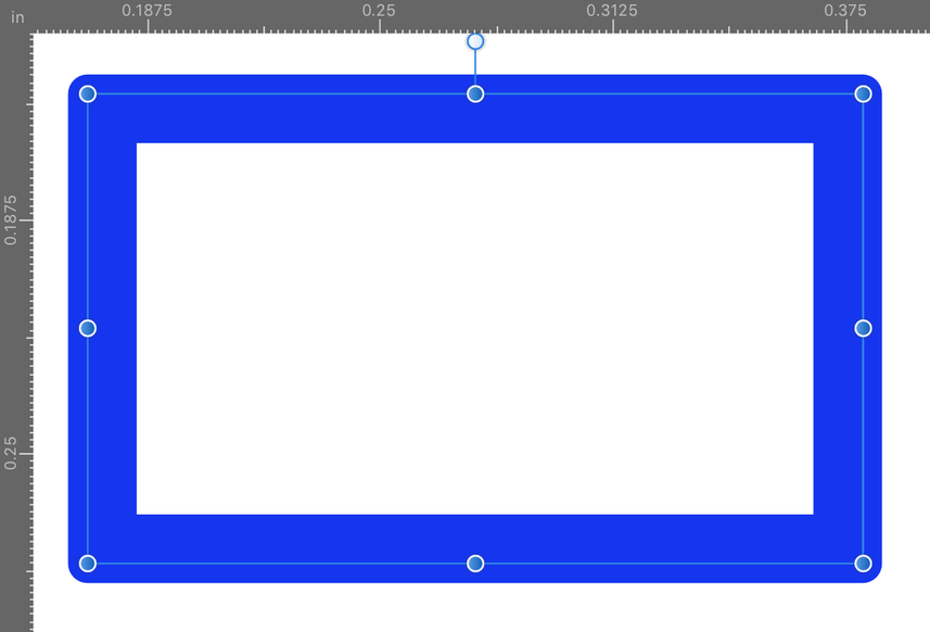
6. Select your finger rectangle and expand its stroke.
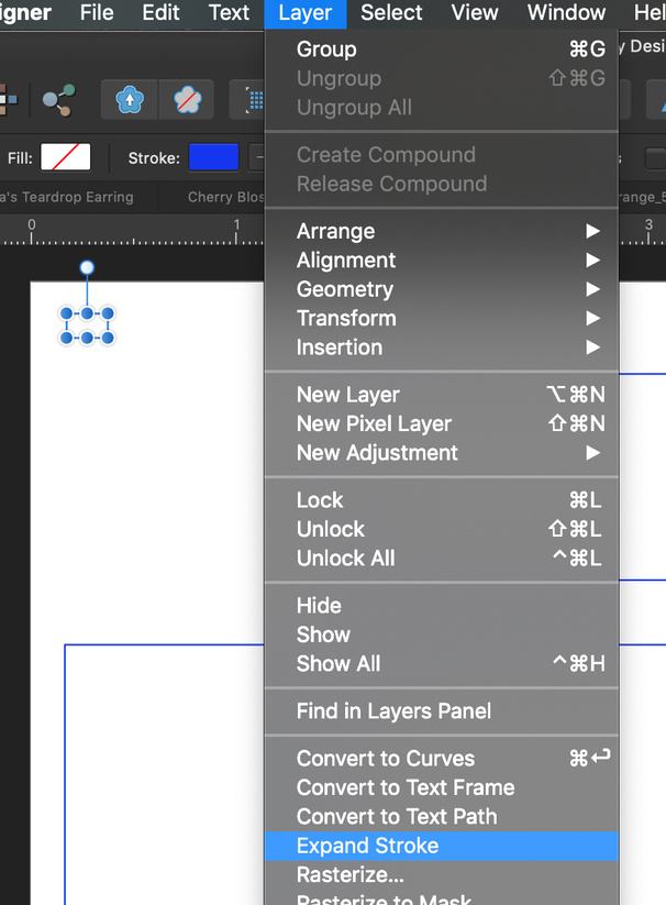
This creates two paths, one on each side of the previous stroke. Here it is zoomed in, so you can see before and after:
Before:
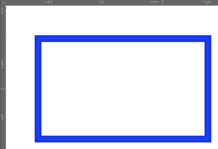
After:
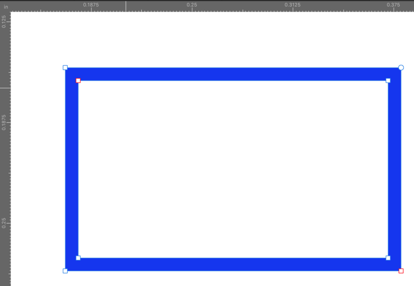
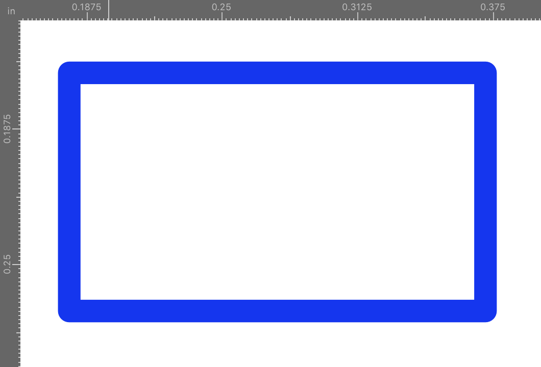
7. Divide the resulting shape.
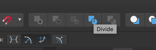
Now it will look like this:
I like to remove the fill so I can continue working just with outlines:
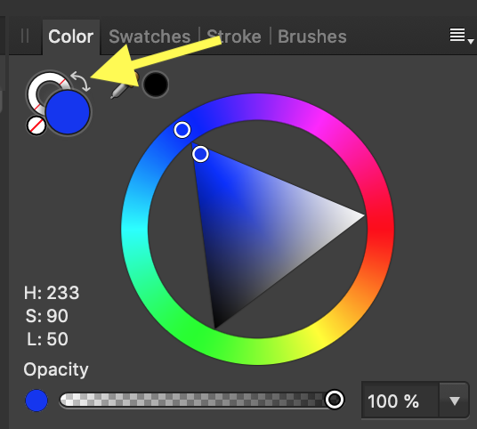
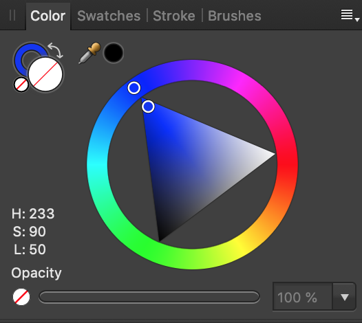
Now it will look like this:
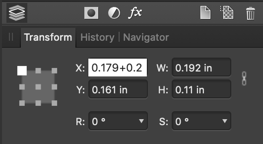
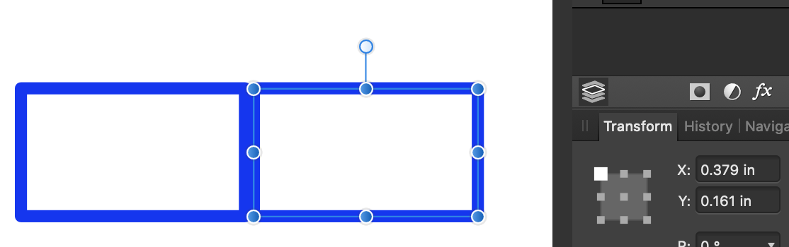
9. Duplicate this rectangle, spacing the new ones at intervals equal to its original width, until you have enough to go across the longest dimension of your design object. You now have a row of finger 'holes' with kerf already built in.
Select your rectangle and do CTRL J (Command J on Macs) to make a duplicate. Place the duplicate by adding the finger width you chose in step 3 to the current X-coordinate.
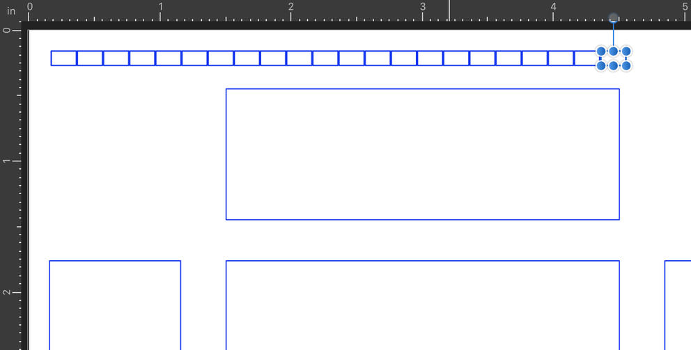
Then continue to place new copies at the same interval by repeating CTRL J until you have as many as you need. (I like to have a few extras, just to be safe.)
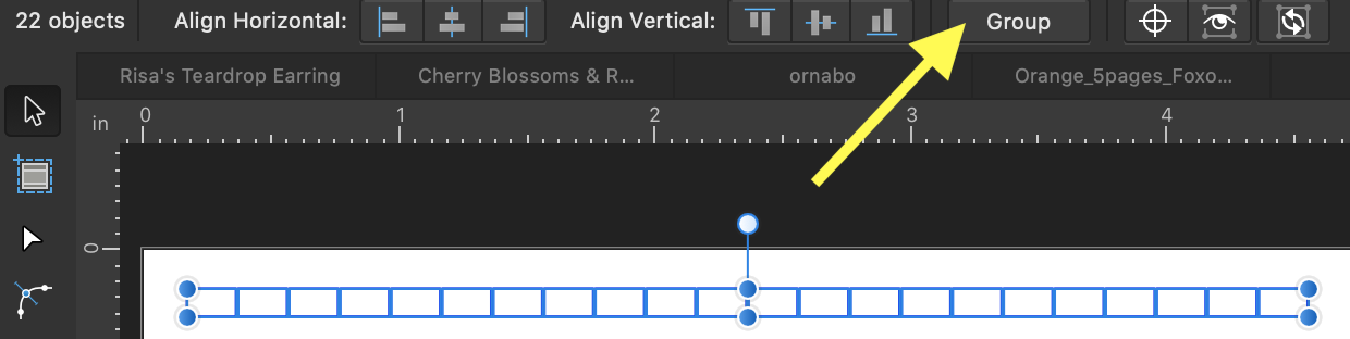
10. Select the row of rectangles and group them. Place them in an out of the way spot in your design. You'll make a copy of this group for creating each row of finger joints.
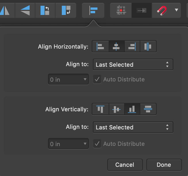
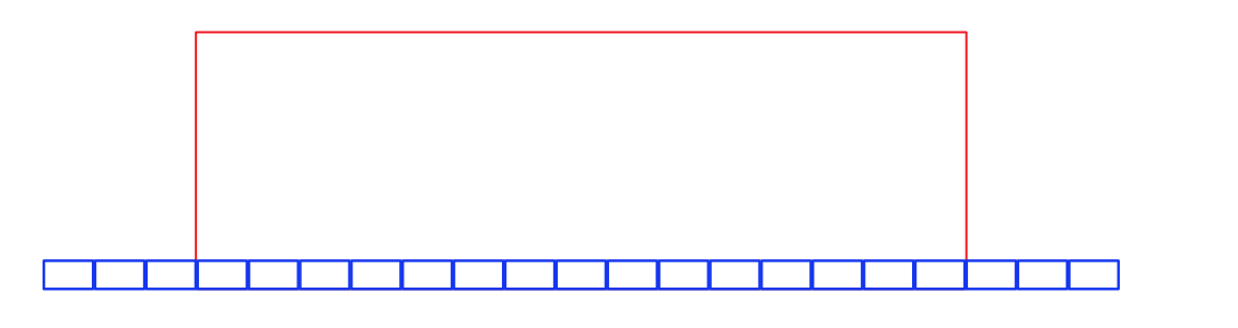
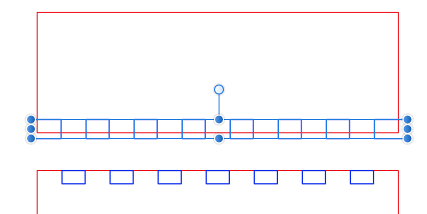
11. Center copies of the finger strip against two facing edges of your design.
To align, select the finger strip first, hold down the SHIFT key, and select the object you want to align it to. Then use the alignment tool to choose where you want the strip to go in relation to the object. In this case, I’m centering the strip along the bottom edge of one of my box pieces.
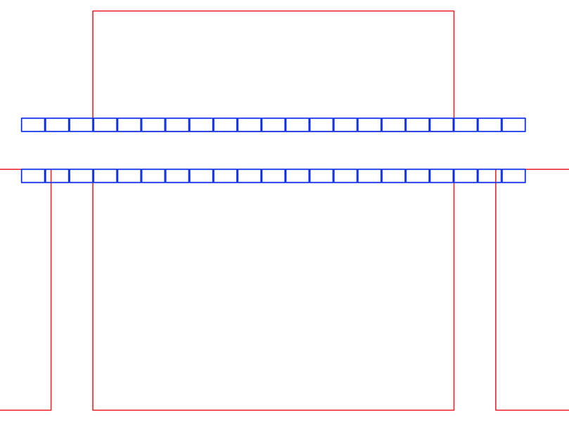
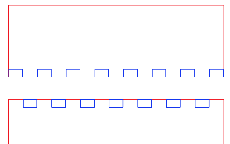
And here are the finger strips placed along two facing edges:
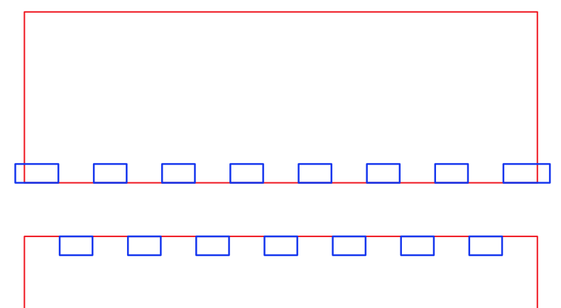
12. Look at where the fingers/holes line up at each end of the object. If the spacing is awkward, ungroup your finger strip, delete one rectangle, regroup it, and recenter.
Here I’ve ungrouped one of the finger strips, deleted the excess, and deleted every other rectangle to get a feel for how they would fall along the edge.
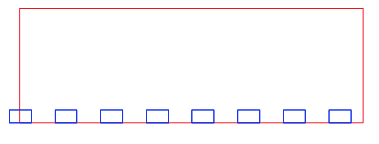
This spacing is awkward, since it leaves me with half a finger at one end and half a “hole” at the other, so I’m going to try again by deleting one rectangle from my original finger strip and re-centering it.
I like this better. If the strip of holes and fingers doesn’t end up exactly at an edge of your piece, you can make small symmetrical adjustments at each end. In this case, the last “hole” or “finger” at each end will be just a fraction larger than the rest, but it will look fine as long as it’s symmetrical.
Before doing anything else, copy this new finger strip to the opposing piece, so you can work on them at the same time.
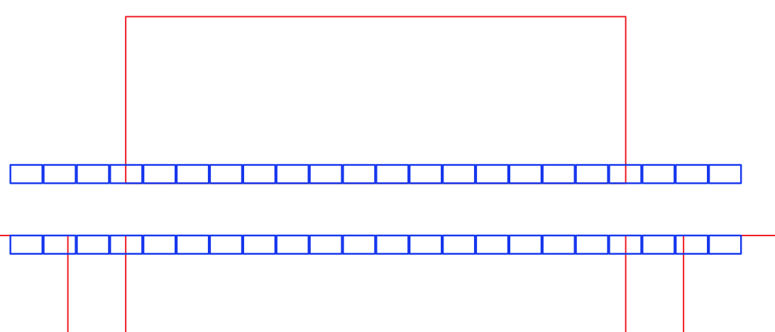
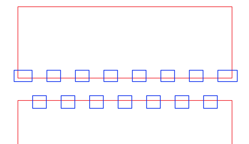
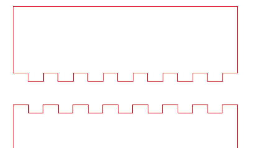
13. Now ungroup the strips and delete every other 'hole' along one piece, and the opposite ones on the other piece, so they will fit together.
14. When you're happy with the placement, stretch the end rectangles to make sure they overlap the ends of your piece, then stretch the entire strip to overlap the edge they lie along, to ensure you won't have any wonky little nodes left hanging out in space after you merge them.
End “holes” stretched:
Stretching the whole strip over the edge:
Ready to merge:
15. Subtract the row of 'holes' from each of the two pieces.
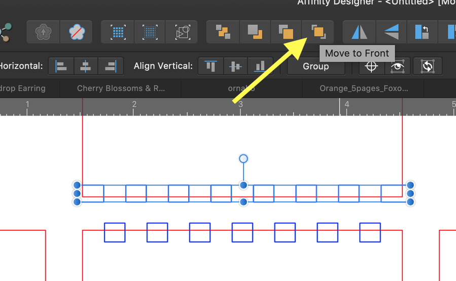
Select the finger strip and move it to the front. This ensures they will be the items to be subtracted:
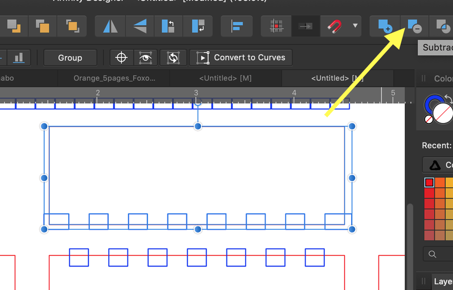
Hold down the SHIFT key and select the object below them, then click the Subtract icon in the top toolbar:
Repeat for the other side:
Now just repeat this process for each of the other sides of your box. Repeat the same sequence, rotating the “finger strip” by 90 degrees to do the vertical sides.
Remember to keep that original “finger strip” intact while you work, so you don’t have to go back and rebuild it!
EDIT: Added a step (#3) for checking fit and making adjustments to finger width if desired, before adding in the kerf.


