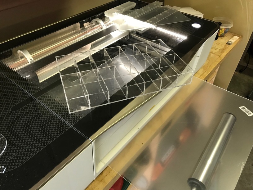
I got the Pro so I could have over sized material stick out the front while I cut pieces out of it. Home Depot sells Glowforge ready 20" x 32" x .092" sheets of acrylic. I am making embroidery floss holders for my sister. (Don’t tell her. It’s for Christmas)
So I cut a bottom part out of a full sheet and had to figure out how to most efficiently cut the next bottom part. Then I realized I could just push the sheet forward and let the rest of the sheet poke out the back while I cut the part out right next to the previous operation.
PRO!!!
Bonus:
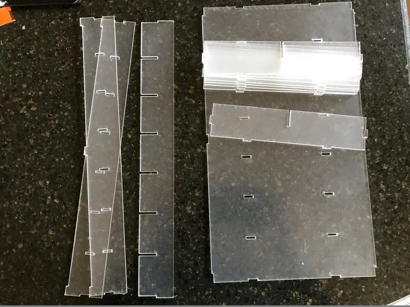
I am working on a power settings spreadsheet. It has thickness, power and speed. But I also have columns for Tabs and Slots. When I figure out how a material reacts to the laser kerf I document what sized tab fits in what sized slot. I work in metric and these are my setting for 5mm tabs in this material.
Home Depot .093" thick acrylic
Operation: Cut
Speed: 200
Power: Full
Tab: 5.25 x 2.4 mm
Slot: 5 x 2.2 mm
Great job. You have figured out the same thing I have on kerf. Effective kerf varies by what you are doing. I record mine as an offset from zero though. Most plys run around .21mm for instance.
Yeah I will probably get to something more scientific in my documentation. But right now as I am working a tab & slot situation in a new material I note those specific measurements. I’ll do the math later.
I am pondering my spreadsheet and kerf widths. I am curious about how you design. Because I found myself flip flopping. Do you make a tab at a certain dimension and take the kerf out of the slot? Or slots of a specific size and the tabs adjust to fit? Or am I thinking about it the wrong way?
With automatic kerf correction in some software, it’s usually 1/2 kerf on both because the way it shows up in many UIs is “cut outside”, “cut inside”, “cut on the line” and the software uses 1/2 the tool diameter to get there (for spinning cutters).
I do all of my 3d design in Fusion 360 and usually use a plug-in to export dfx with half of the kerf compensated for on each side of the joint.
More and more I am designing parametricly and adjusting for kerf in the design. One great thing about doing it this way is if there is a compelling reason in your design, you can put all the kerf on one side.
Yeah that is where I design too. I want to figure out how to use “Parameters” better. That may be a good way to adjust kerf to a project. Right now I am in love with the Shaper SVG plugin for Fusion , so I may be overlooking other good plug ins.
Okay, great, you know how to install a F360 plug-in. Go to the store and get the DXF for Laser cutting plug-in. It will output a DXF that you will need to run through Inkscape or AI to convert to SVG but it has kerf compensation built in.
I love the Shaper plugin as well but you have to do all your kerf work in your file.
I won’t EVEN try to couch you on parametric design as I’m not super good at it myself. There is lots of info here if you don’t mind doing some searching.
Thank you sir! I will give it a try. As I learn Fusion 360 getting my sketches fully constrained so the parametric design works properly is my current white whale.
The Shaper plug in still requires Inkscape manipulation because it fills in the strokes and GF sees that as engrave. So I can tweak a DXF out of this other plug in. Downloading!
I have a bit of a public one going if you care to contribute. Other wise I’m excited to see your sheet! Just follow to the Google doc, it’s in there somewhere.
You and I both brother, you and I both. And I hate to be Donny downer but a fully constrained sketch is not enough in a lot of instances. You have to take it on to properly fully constrained. The good news is parametric is not an all or nothing thing. All F360 designs are parametric to a degree, we just add user parameters and try to make the finished model as unbreakable as possible.
True and untrue. True that the GFUI initially sees this as an engraving but untrue in that you don’t have to run it through Inkscape. You can convert to a cut right in the GFUI!
I was up till 6AM working on my F360 Parametric box maker. I finally had to give up with two variables not working. I got them fixed the next morning when my head was clearer. I can’t figure out how to set an origin point, so as I increase the size of the sides, they collide with each other, I solved this by putting the parts on separate sketches for now. Another issue I ran into was making lines parallel at a parametric distance without the use of construction lines. Since construction lines export with everything else, I need to delete them when I import to Inkscape.
Having to import to Inkscape to export as SVG is bogus. I hope they get DXF built into the GFUI soon!
Sounds like you are out in front of me with parametric, I’m usually quite happy if my model doesn’t break when I tweak the material thickness more than a few thousandths.
I agree that getting DXF to go native should be a priority but if you are adjusting for kerf in your model, use the Shaper plugin, it won’t pick up those construction lines as it will use the face of the body.
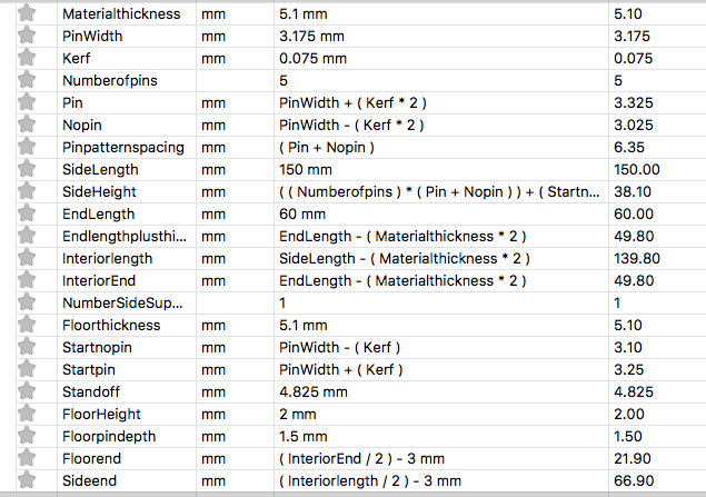
I got Kerf parametric in the model I drew the pin profile normal, then used offset with a sample 1/2 kerf spacing to get the off set, then figured out what the width of the pins and nopins would be. I found that there were 4 different sizes of pins for the sides and the ends.
I wish there was a way to reorder the list, or better yet provide a simple dialog box for the user input variables. Currently I have to scan through the list to find my inputs.
The parameter list looks like this.
User in puts are:
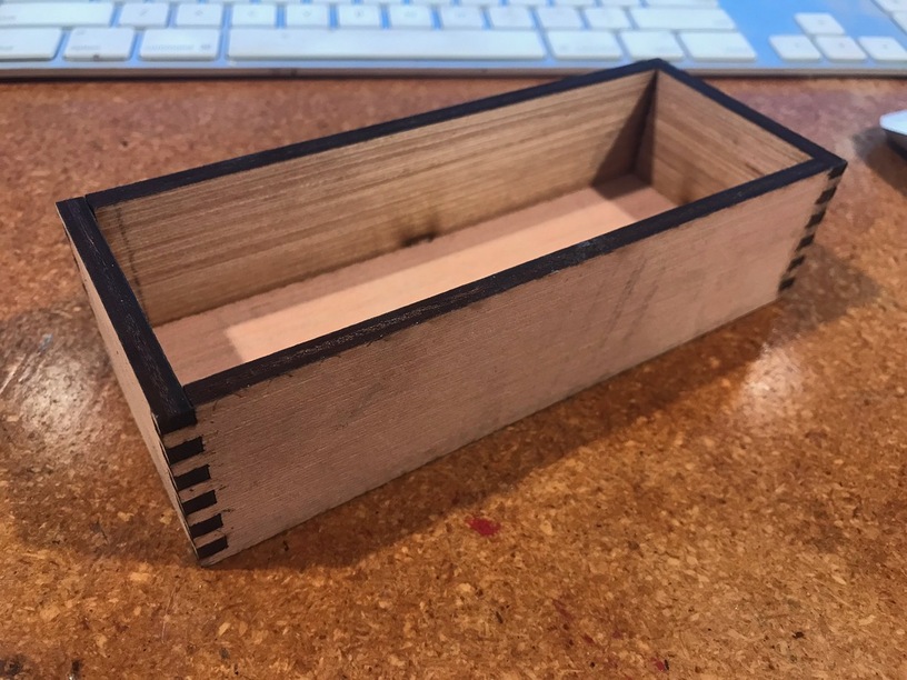
Material thickness, Length of side, length of end, how thick the floor is, and how high off the bottom you want it. The number of support pins for the floor, and how deep you want the pins on the floor. For the Pins and finger variables, there is material thickness (how long you want the pins) How thick the pins are. The model is driven by how many pins high you want the model. That way all the pins wind up a uniform size. I like my pins small in comparison to most of the designs out there. Its a personal preference and gives a tremendous amount of glue surface. The joints are incredibly robust!
I will probably be making a lot of them in pine or Maple but
 plys run around .21mm for instance.

 that is why we come here. I expect that you will return the favor one day.