I initially posted this issue on Beyond the Manual. I’m putting it here now as I think it is more fundamental than just the 6mm acrylic I’m cutting. Thanks to @eflyguy for ideas on the other thread. I’ve made some edits from the other thread to make my comments more accurate/precise.
I am making an assembly out of 6mm thick cast acrylic (clear). I have one piece that has tabs that insert into another with holes (perpendicular parts). I carefully calibrated for the kerf and used the measured kerf in Fusion 360 to generate my design files using the colorific plugin. In order to increase clearance and allow parts to slip together, I intentionally reduced the kerf width inside Fusion 360 by 100um.
With some parts this worked great, but with my 140mm diameter disk (with holes to insert tabs) the hole size varies from place to place. If this were a clock there would be a tab hole at noon, 3, 6, and 9. Each slot size is different. I get a loose sloppy fit at 3, but can’t fit at all in 9 without forcing it. At 6 and 12 the fit is too tight, but a bit looser than at 9. (In this description noon is towards the resting position of the gantry and 3 is towards the magic button.
The obvious concern would be that the part was not flat, but I think it was. I’ve double checked the remaining acrylic and it is perfectly flat. There was nothing in the crumb tray tilting the part and there was nothing under the crumb tray.
I cut the part again using 6mm thick black cast acrylic. Same exact result. I double checked that the crumb tray was flat and there were no scraps under the acrylic.
I measured the thickness of the acrylic from one side to the other. It varies by about 150um (out of 6mm) on the black acrylic and 80um on the clear acrylic.
After a suggestion by @sqw I cleaned all my optics and repeated my cut. Results with nearly identical.
I checked level of the top of the crumb tray and the top of the cutting head. Both are as level as I can measure with my phone. My crumb tray is fitting perfectly into its grooves.
If I’m looking down at my component laying on the crumb tray (with the laser to the north and the button to the east) . The following information holds:
East - by far the loosest fit. The slots are largest on this side. They appear to be larger with regard to both the N-S and E-W dimensions.
West - appears to be the tightest fit.
I do have a set of calipers. Measured from the top of the crumb tray to the top of the laser trolly (has glowforge logo)
NW - 114.2mm
NE - 114.2mm
SE - 113.8mm
SW - 113.9mm
There is some apparent variability here, but I don’t think that it is likely more than my error in placing the caliper reliably.
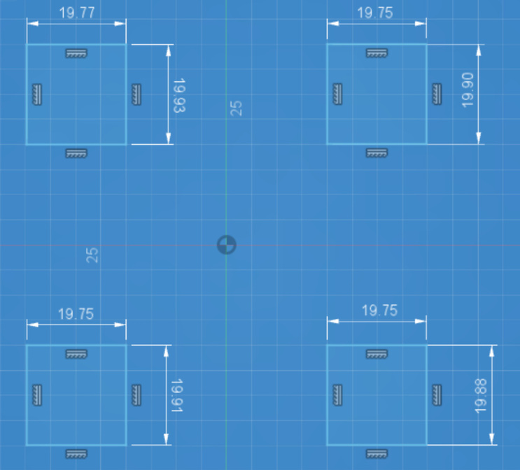
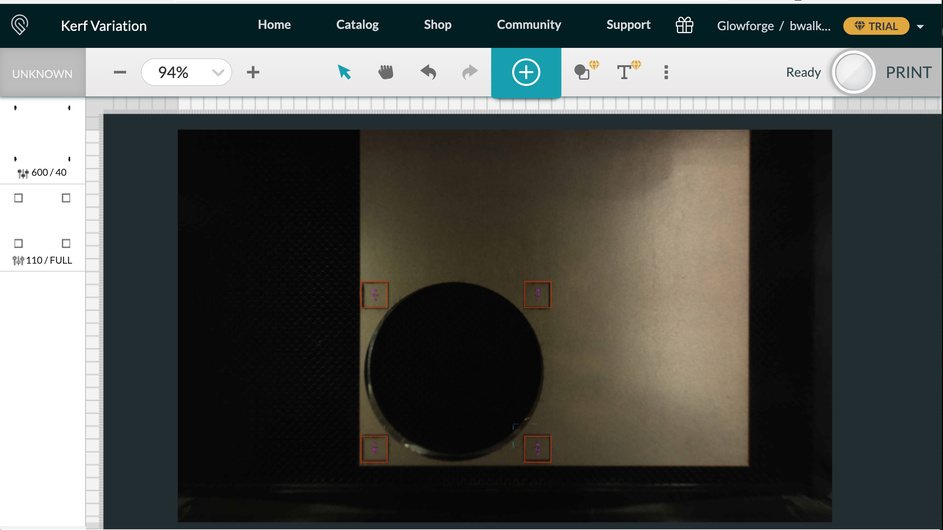
In order to quantify the error I made a simple design with four 20mm squares. I placed one at each corner of the circle (in my scrap) as shown in this screen shot.
I then used digital calipers to measure the height and width of each square. The measurements are shown in this figure.
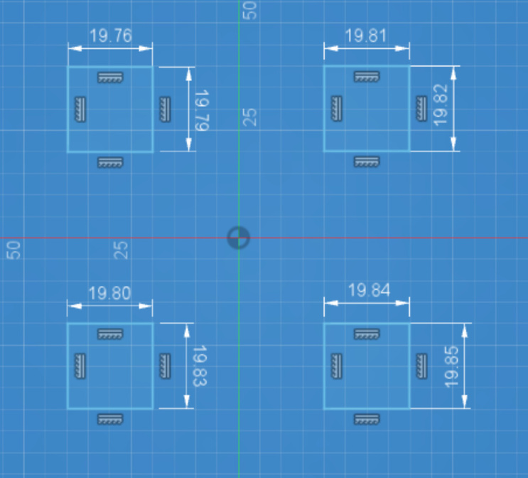
We see that the vertical kerf varies by as much as 60 microns and the lateral kerf varies by as much as 80 microns. This seems like quite a lot to me. Certainly a limitation for any sort of precision machining, which is why I bought the glowforge.
I have to suspect that this is a power fluctuation because of beam misalignment. I should note that in the process of trouble shooting this issue I found impact damage to one corner of my crumb tray. It is not enough to mess up the planarity of my tray, but it suggests that my system took a beating somewhere along the line. It must have been during transit, because I’ve babied it.
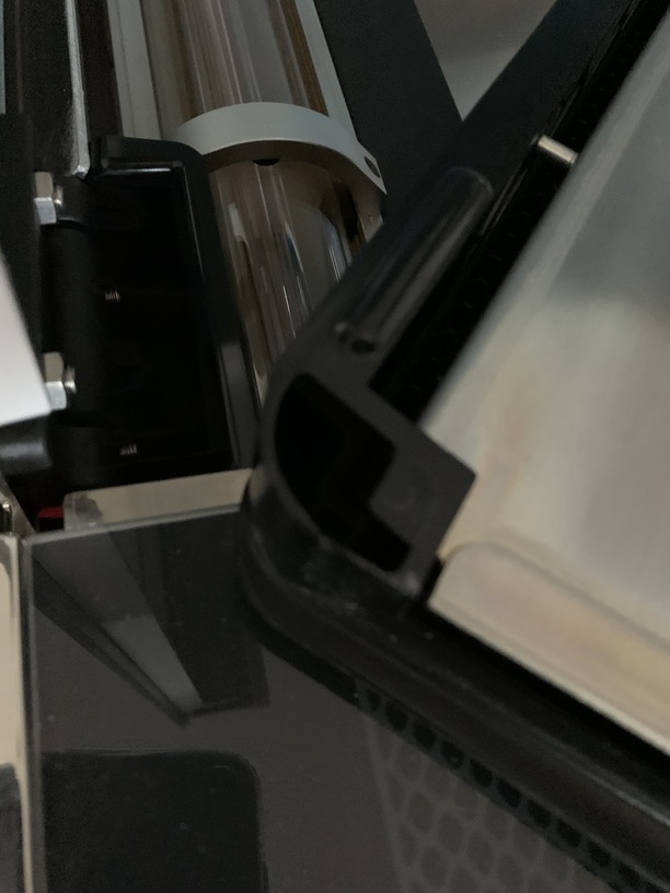
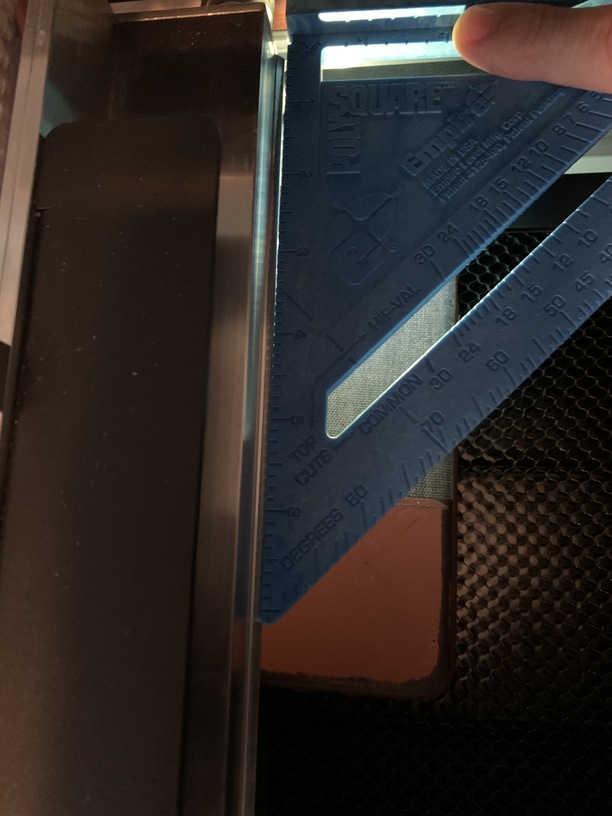
In reading related issues it occurred to me that perhaps the gantry was out of square. I went ahead and followed the gantry squaring procedure as described in the support section. I was unable to square the gantry, as shown by the following photo.
So, I’m unable to get a consistent kerf from position to position. Additionally, the depth of my etches also varies from position to position. (I’m trying to make a groove to hold an o-ring in place). I am starting to suspect that my system is out of whack because it was damaged in transit. Specifically the damaged crumb tray. (Shown below.)
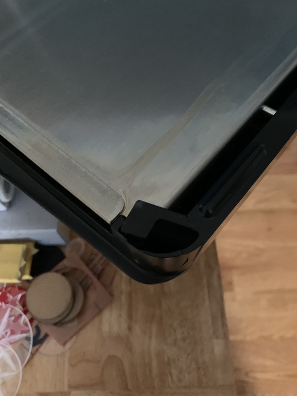
Undamaged corner for reference.