I have a Basic Glowforge and a BOSS 1420, my GF is a 40w and the Boss is a 70w.
I love the software that comes with the Boss, which is Lightburn.
I do a lot of my vector and image editing in Lightburn and export it.
Lightburn and Boss go off of mm/s for the X-axis speed, what does GF use?
There are some files I have where I need to use, ie. 340mm/s 18 power or 250mm/s 25 power, on the Boss, but what would be the conversion for GF?
Part of why I’m asking is I am also trying to figure out how to use the Norton White Tile method on my GF, if anyone is familiar with that.
As for speed, someone graphed it out. As I recall, the glowforge speed numbers equate to a nonlinear real speed, as in speed 100 is not half as fast as speed 200.
Hopefully someone knows where that post about real speed numbers is can swing by and tell you, but in the meantime those posts about the Norton method should get you going.
Thank you, as soon as I posted my question and scrolled down I saw a post about the NWT method lol Figures!
The speed conversion would still be nice to have esp since one laser uses mm/s and the other doesn’t.
The Glowforge is a cheap hobby-grade machine. As such, it does not strive to conform to any kind of standards.
Commercial/Industrial oriented machines, which cost significantly more, do. Edit - apparantly even those don’t follow any standard like that.
Don’t get me wrong -it’s FABULOUS. I love it. Had it for years. Works great. It’s opened up the world of laser cutting to the crafting community, and that’s absolutely wonderful.
I guess I can see what you mean by that then. My Boss laser definitely cost me significantly more than my glowforge did and it does run the industry standard of mm/s or even in/s
That’s how it seemed to be referenced in other places I had seen, such that you could take settings from one type machine and “translate” to another. Post amended.
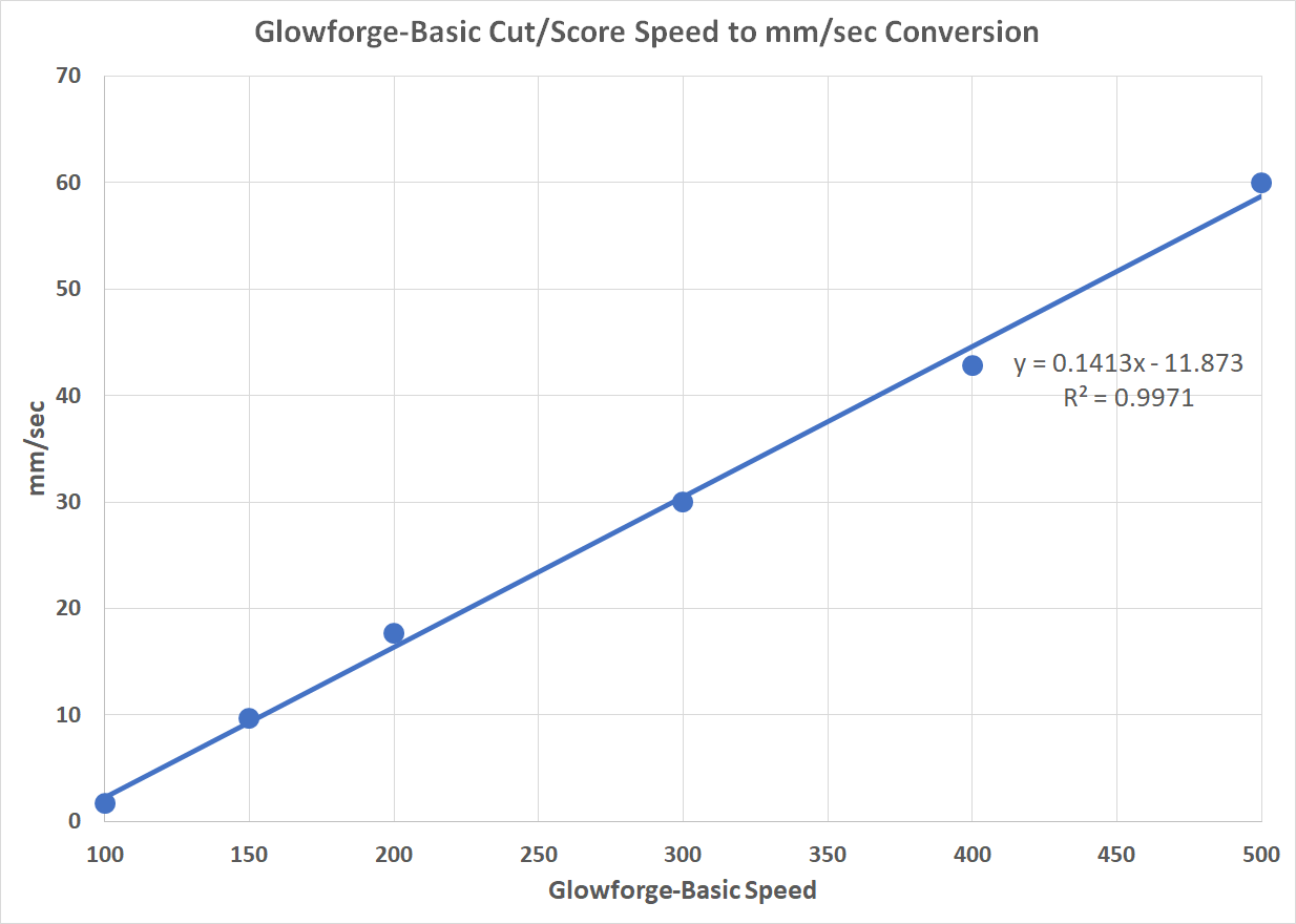
The Basic Glowforge. This is how I got the data:
I created a 300mm line to be cut and tried different speeds (e.g., 100, 150, 200, 300, 400, 500) and started to print. Once the GF app showed how long the print would take (in seconds) I recorded the values. For the speeds above, I got the following times: 177, 31, 17, 10, 7, 5, respectively. Each time, then, is how long it will take the GF at each of the speeds to cut a line that’s 300mm long. I divided 300mm by each of the times to get mm/sec for each speed. That resulted in the following values for each speed (1.69, 9.68, 17.65, 30.00, 42.86, 60.00). Therefore, Speed=300 corresponds to 30.00 mm/sec and Speed=500 corresponds to 60.00 mm/sec. I fit the data to a linear regression to get the other values.
As bought up in another discussion recently, the GF has a lot of “magic” built into it that insulates all these technical intricacies from its users. Trying to reverse-engineer it is futile.
I decided that a better way of measuring the cutting speed was to video record cutting a 300mm straight line and a circle with a diameter of 95.5mm that results in a circumference of 300mm. I recorded runs at GF Speed settings of 100, 300 and 500 and used the video data to determine the exact start and stop times of the cut so I could calculate how many seconds each took. I could, then, calculate mm/sec by dividing 300 by the number of seconds for each cut. Here are the results:
These data confirm what you said about the speed changing between straight lines and curves and illustrates that my dependence on the timing from the GF was not a good idea, at least for straight lines. I will collect video data for the other speed settings and reconstruct my graph.
However, I think this also illustrates your last comment about reverse engineering the machine. I don’t think that’s going to happen. I’ll be happy to have reasonably close approximations for actual speeds for the work I’m doing.