The trouble with just these tho is that few designs in practice are just straight lines and circles. (Puzzles and 90% of the catalog for examples) This also doesn’t take into account the head moving around the design when it’s not firing - which is often not direct or efficient path and can change per run of otherwise identical jobs.
Right, but all I want to know is approximately how fast is the head moving when it’s cutting. The total length of non-cutting movement definitely will vary with each job and that will affect the total time to finish. The cutting speed can’t vary that much or else you’d end up with incomplete cuts in places.
Ah but it can, and that’s the magic - because they change the power as it goes to compensate, depending on the speed of the head.
Even “full” power isn’t max all the time.
2 Likes
Magic, for sure!
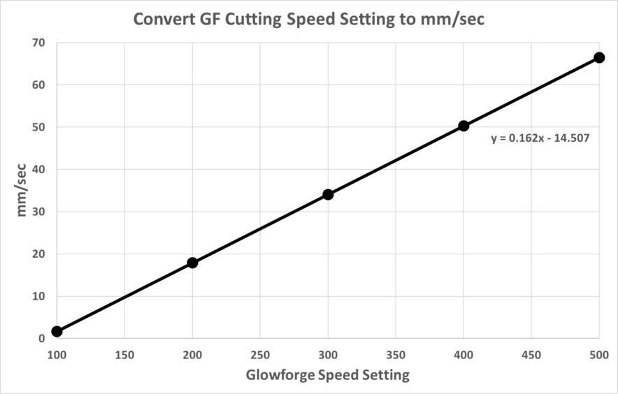
The spreadsheet that I linked to a while back is straight from Glowforge. It is their basis for speeds. Not sure why you wouldn’t use it, or use the formula to chart it?
As far as the power modulation, there would be no need for it if the speed wasn’t also modulated. Unfortunately, no system can traverse through all geometries without slowing down to some degree.
4 Likes
The spreadsheet provided by GF was the opposite of what I wanted. Their spreadsheet calculated the “new” arbitrary speed numbers from the “old” values that represented actual movement of the laser head (e.g., in/min). Plus, I’m accustomed to working in mm/sec. I’m sure I can’t take into account all their “magic” with modulations of speed and/or power. I just want to have a better idea of how fast the head is moving in actual rate units (e.g. mm/sec) instead of numbers that have no units.
Right, but the formula just needs to be rewritten to go from new to old and then converted to mm/s. It’s kind of like the formula for mm to inches, and then applying it for inches to mm.
3 Likes
Yes…I’m working on that now.
This has been a very interesting discussion and I’ve learned a great deal. I thought I’d finish it off by showing a graph of actual cutting rates (mm/sec) for GF Speed Settings for three different types of shapes (line, circle, angles) that are all 300mm in length. I don’t know how useful it is, but it illustrates many statements made by those participating in the discussion. Thanks for those! This is the image used for the testing:
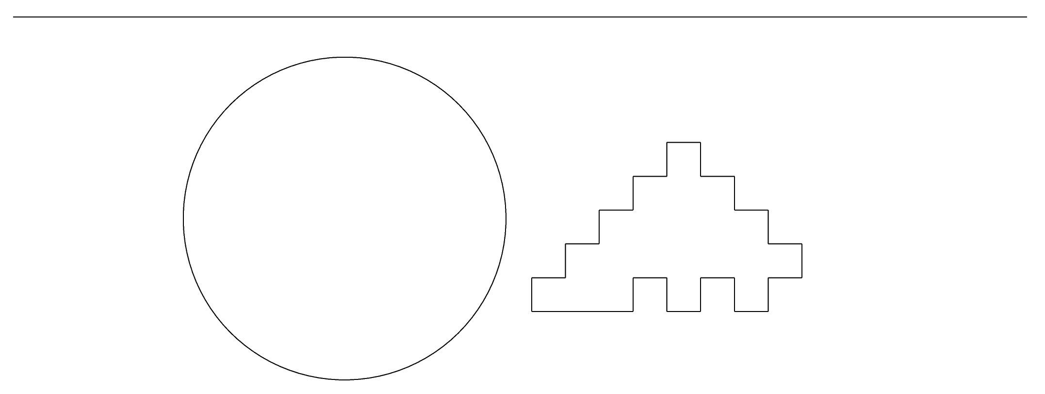
I video recorded each print at GF speeds of 100-500. From the video data, I was able to determine the number of seconds for printing each shape at each speed. From that, I calculated mm/sec for each GF speed setting for each shape. Those results are graphed below:
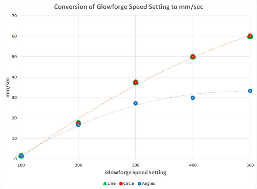
The mm/sec for the line and circle were essentially identical. Printing the shape with all the angles (even though it, too, was 300mm in length) was significantly slower.
2 Likes
This is due to all the sharp corners in that shape. It has to come to a stop at each corner to change direction, due to the momentum of the head. Whereas with the circle it doesn’t have to slow down because it can smoothly change direction.
2 Likes
I think from this we can surmise that the circles you were running in your power test were probably not affected by speed modulation (thus power modulation); 100 speed is glacially slow and despite the weight of the head, should be able to handle just about any shapes with radiuses without decelerating and modulating the power.
This is also one of those lessons that can be applied to cutting very thin materials, or running scores, that have very intricate geometries. It’s very possible to obtain a higher average speed using a slower prescribed system speed.
3 Likes