Recently I undertook a (project) and I thought I’d detail a few of the processes I’ve been using since I haven’t seen anything exactly like this. Apologies if it’s been covered before.
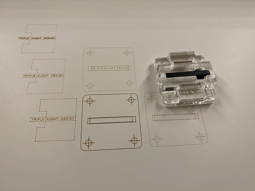
My method for making a jig for repeatable object engraving is to make it out of clear acrylic and engrave fiducial marks on the bottom of the the jig, so when it is flipped over, the marks are directly on top of the surface the jig is sitting on.
Then in my project file I have the engraving to be done as well the fiducial marks and I score them onto a sheet of card that is taped to the crumb tray. Once that is done I can drop the jig onto the paper and align it so that when the engraving is done everything lines up perfectly.
For objects that can be aligned in a single sheet of acrylic this is quite satisfactory. It saves having to cut a new jig each time I do a production run. (Previously in order to get satisfactory alignment I was cutting a jig out and then not moving it at all for the production run. This way the jig can be reused and the only waste is the paper it sits on.
So far, so good, this is all pretty typical jig making for the Glowforge.
In the case of the pen clip jig, it required a multi layer design with cut and engraved pockets to hold the object. The problem is in aligning the bottom layer of the jig which necessarily has the fiducial marks on it’s bottom with the top layer which holds the workpiece.
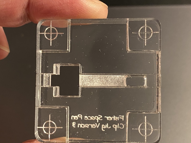
In this case, working with such a small object, eyeballing and gluing the two pieces did not provide sufficient accuracy. In the next image you can see that the cutouts for the workpiece are off by a fraction of a degree from the lines. On a <4mm tall clip, this was enough to be noticeable.
My solution is to utilize the natural kerf of the laser cut to make wedges that hold the two pieces together while also aligning them perfectly.
In this particular case, the alignment holes were 3mm x 16 mm rectangles. Using the stroke width method in Inkscape to adjust for kerf (in this case 0.15mm) I get two sets of lines. An outer cut and and inner cut. The outer cut should result in a cutout of nominal dimensions 3x16 and the inner cut results in a hole of the same dimensions.
Since each of these is actually not an up and down cut but a wedge due to the nature of the cut, a cutout from the outer line if flipped upside down will almost exactly fit into the hole made from the inner cut. Hard to see, but the wedge is actually placed into the hole in this picture and fits in exactly like a perfectly fitting inlay would, from both the topside and the bottom.
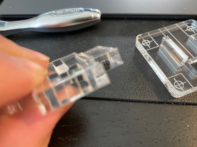
Since the upper and lower parts of the jig are flipped,the smaller ends of the alignment holes abut each other. Here you can see the wedge placed into the hole in the flipped bottom part of the jig. It just barely fits.
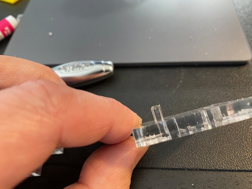
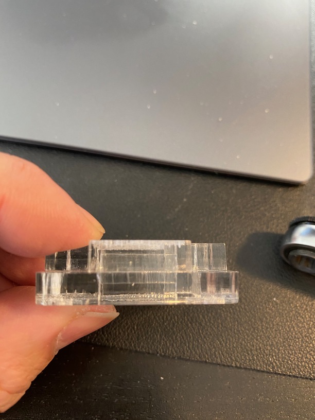
Once the jig is assembled, the wedge can then be lightly hammered into the hole through the top piece and into the bottom, creating an interference fit that securely holds two halves of the jig together and also (and more importantly) aligns the holes exactly. Here you can see a side view of the assembled jig. The wedge can be seen hammered in and it sits halfway into each layer.
Theoretically this could be used in any situation where you want to join two layers together mechanically without glue. The key is to use kerf adjustment to make sure the dimensions of the ends of the two holes that abut each other are the same. The shape of the wedge used to join the two pieces need not be square, and could even be decorative in nature.