Thanks for your help. I will conduct the experiment and let you know what I find.
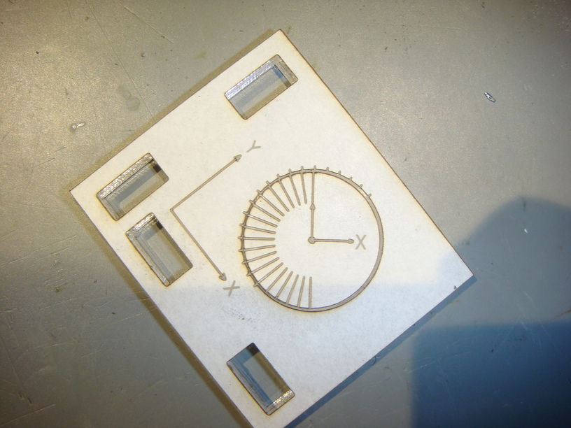
@jaz I have conducted your requested experiment. I adjusted the design slightly to give you as much information as I could think of. What I observed is that the circle would not turn until I broke it free of the mating part. It did not cut completely through.
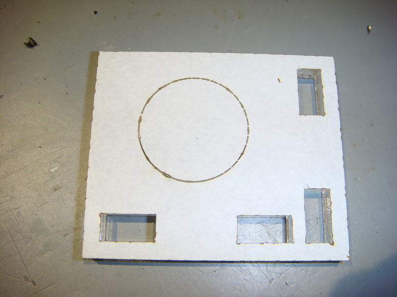
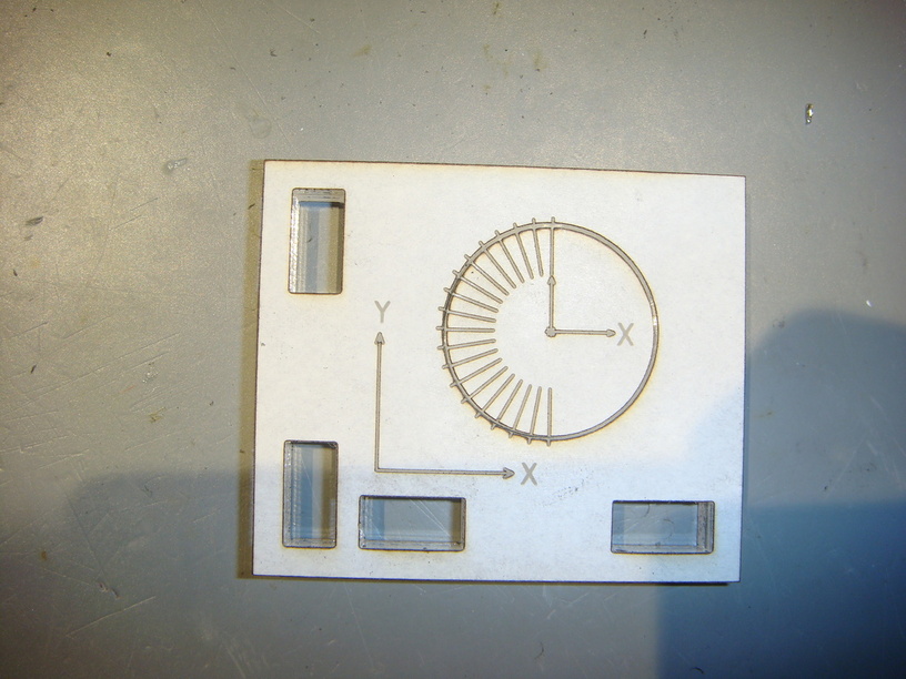
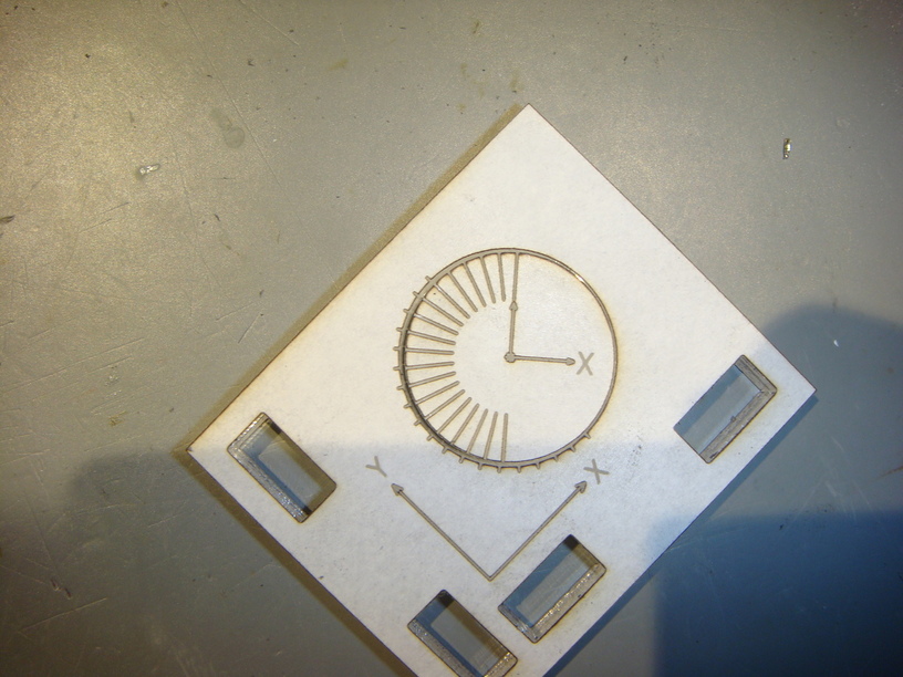
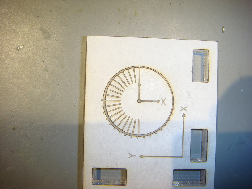
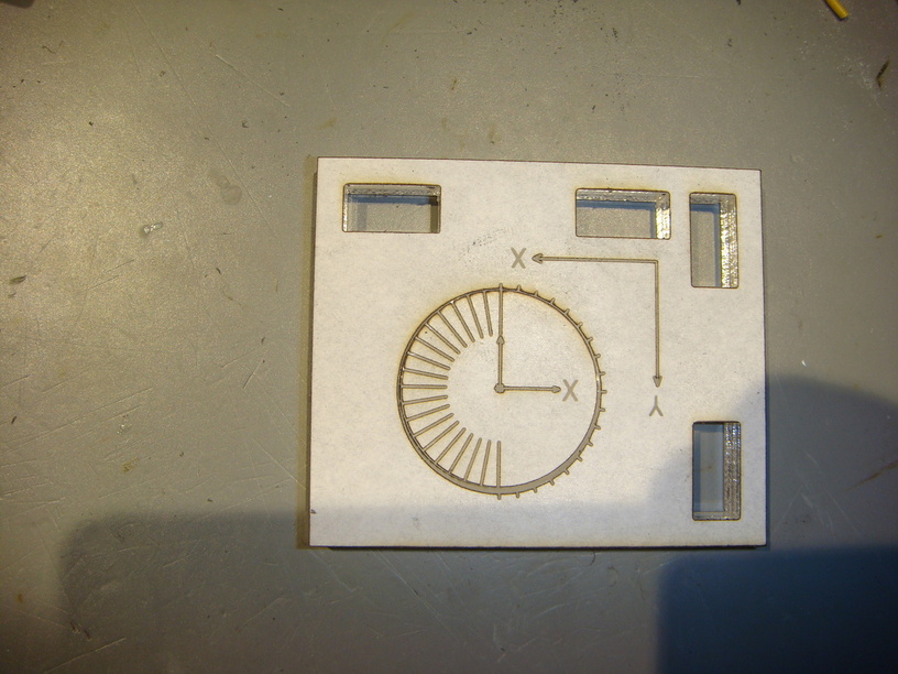
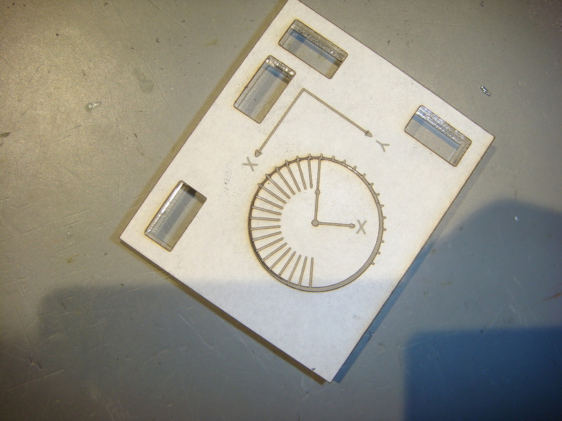
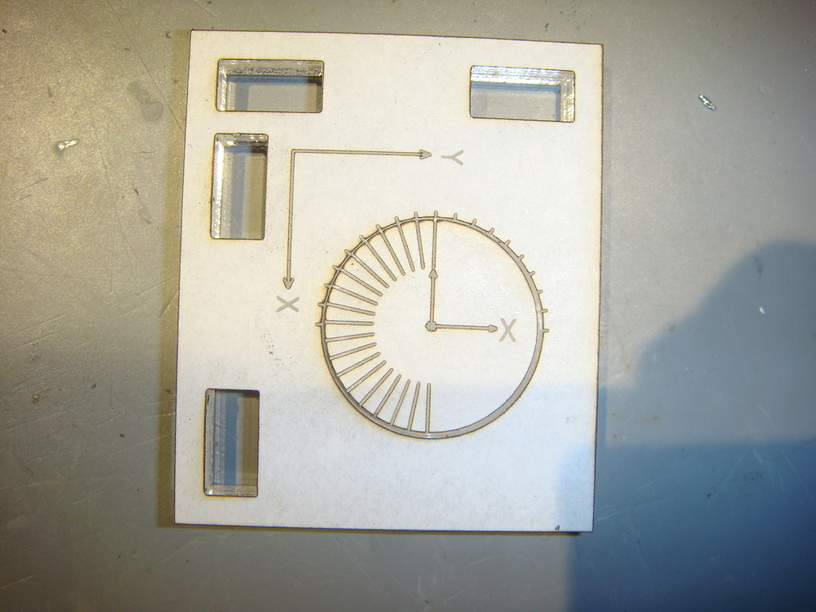
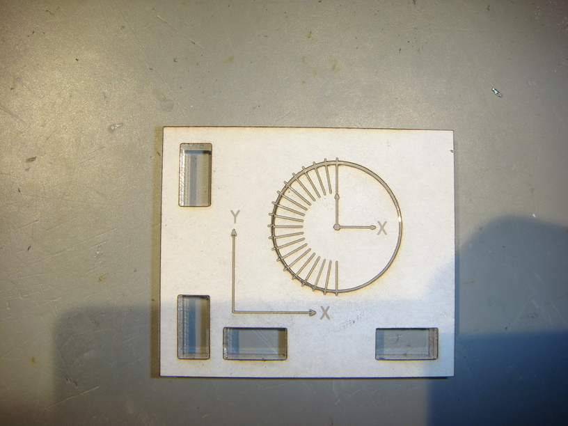
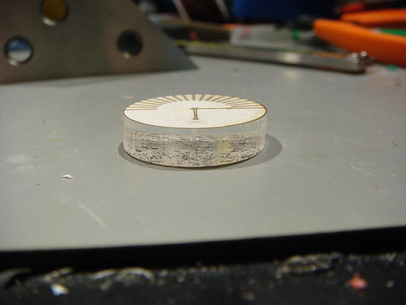
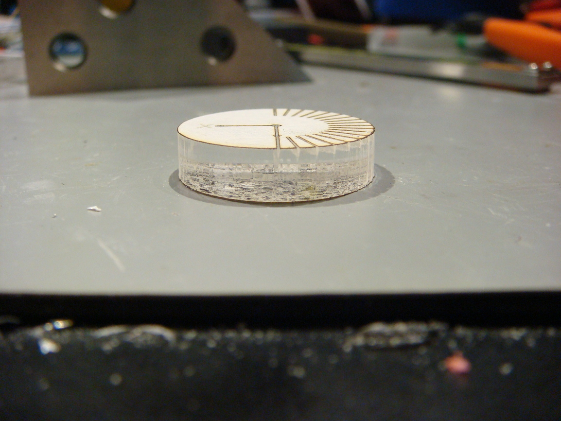
Then I turned the circle and while it turned inside its hole, it did not stay centered. You can see the change in the photos below. Each picture is at about 45 degrees from the last.
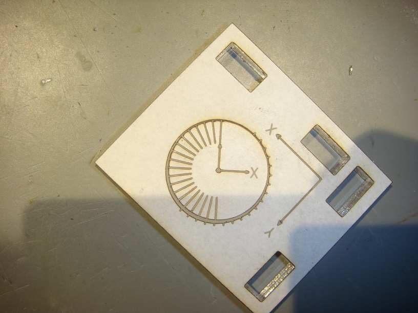
The next test was to see if I could isolate the error to a single axis. The slots in the base are cut to be a tight fit, with very little wobble. I estimate the wobble at about 0.2 degrees.
X-Axis:
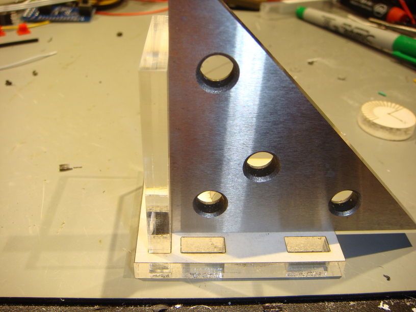
I see a variance of about 0.5 degrees in the X axis alignment, from perfectly square to 0.5 degrees. This gives an approximate X axis error of 0.25 degrees. The tilt is top to the right of the laser.
Y-Axis:
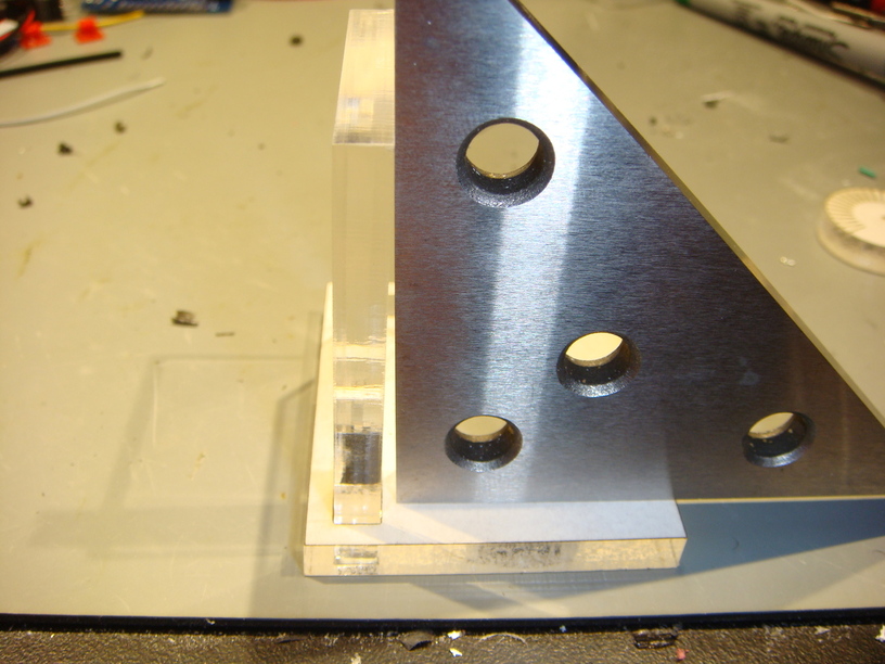
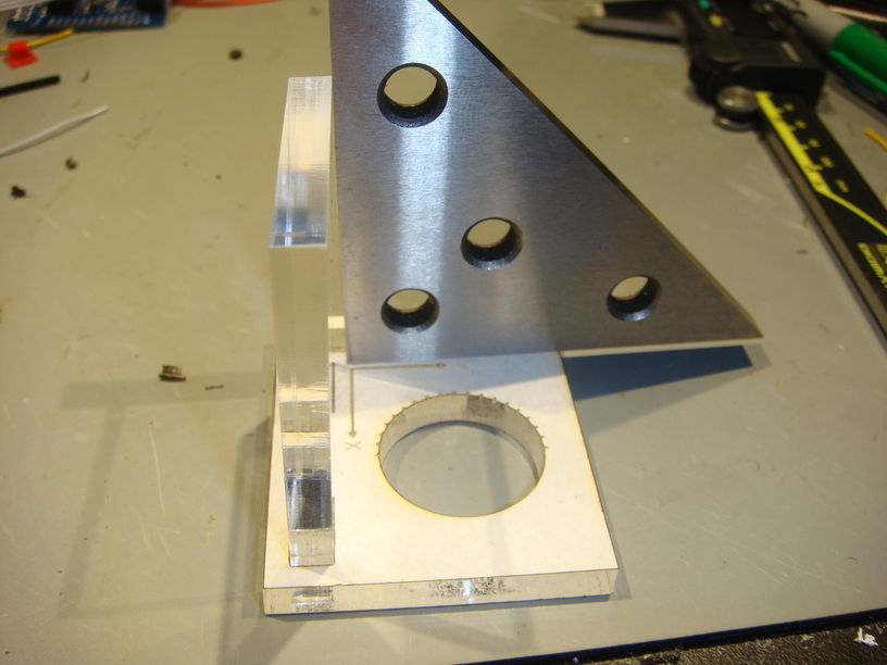
At the base of the insert I measured a gap of 0.075 inches. The tab is 2.09 inches tall at its inside face, measured vertically. A little trigonometry gives an error of 2.055 degrees. With the estimated wobble, I will just call it 2.0 degrees.
I did not see anything on the head or the head support that would lead to the top of the head being tilted toward the back of the laser by 2 degrees.
Please let me know if there is any additional information you require.
Thank you for your time and attention.
:edit: Adjusted error value on X-Axis
3 Likes
I forgot the pictures of the edges! Sorry!
Looking down the X negative axis:
Looking down the Y negative axis:
1 Like
If it will help, I will also send you the parts. Just give me an address.
I had some down time tonight so I looked at the X-Carriage as much as I could without disassembling anything. I found that when I pull up gently on the air assist fan shroud, the entire X-Carriage rocks. It seems to be spring-loaded and drops right back into place, but this action also lifts the back rollers out of alignment with the gantry. I don’t know if this is something that may be causing it.
If GF is willing to provide the information and permission, I think that I could potentially put a set of spacers on the front X-Carriage wheel posts that would shim the X-Carriage to the right dimension. I would just need to have the geometry to calculate the thickness of the spacers. This would save a return.
Thanks so much for doing that!
I’ll keep looking into this and update the thread when I have more information.
Thanks for your patience.
Once again I apologize for our delay. There may be an issue here, but unfortunately, it’s difficult to tell from the photos. I’d like to send you a part and have you send one back so that we can examine it to deepen our understanding. I’ll email in a moment to make arrangements.