I am working on an acrylic box for a client. Part of the box has an insert where a support slots into the side to support an internal component. As I was doing test fits, I noticed that the insert does not fit square into the wall of the box. I estimate about a 1-2 degree angle. For doing flat work, this isn’t a problem for me, but when I am making anything that must fit together, especially when the material is thick, like the thick acrylic on this part, it is causing a problem. Is this within normal tolerance and something I have to live with or is there a problem? I have checked my laser head to make sure it is sitting in place correctly.
Not sure I understand the geometry exactly (maybe attach a diagram?) but try increasing the power or decreasing speed…
Acrylic has it’s own characteristics that you have to work around.
If you are talking about the profile on the cut face not being perfectly perpendicular - that’s a function of the focal point and the shape of the laser beam. (They do not go straight up and down, they are actually cone shaped, with the point of the cone located at the focal point.) Sticking something into a slanted slot might introduce an angle in the insert, if that is what you are experiencing.
Another problem with melty plastics like acrylic is there can be some slump and rehardening on the thick stuff, in addition to the cone shaped thing going on, so you can have trouble fitting parts together if you try to fit the parts too tightly in the design.
You can experiment with shifting the focal point to see if you can get a more uniform profile on the cut, or experiment with the power settings, speed and number of passes to see if a second pass to remove the buildup on the bottom would work. (I believe I remember reading something about that working at some point for thick acrylic, but haven’t actually tested it yet myself.)
Or you could try just widening the slots fractionally and gluing it in upright. (With a clamp to hold it in position.)
Or you can grab a file and shave the edges. (That’s about all I can think of that might work.)
3 Likes
Can you explain what you feel increasing the power or decreasing the speed will do for a cut that isn’t square? Before I change things, I would like to have a reasoned explanation for changing the variables.
The use instance is:
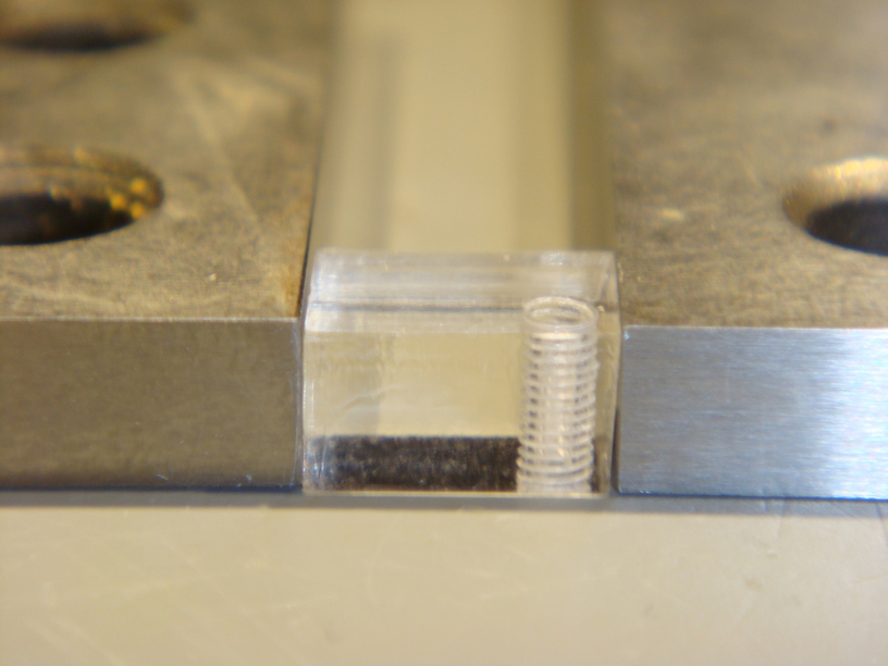
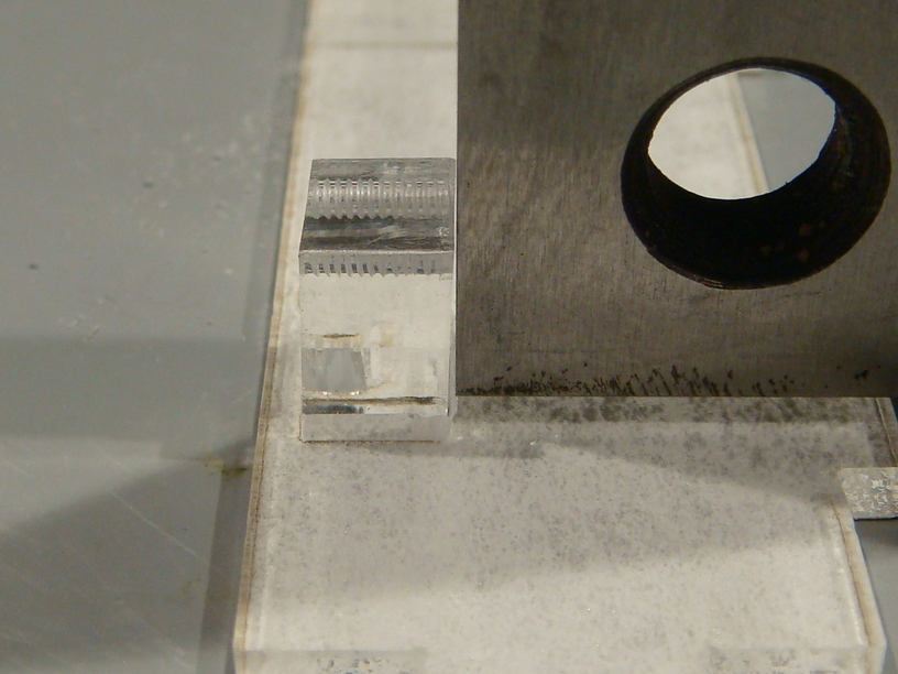
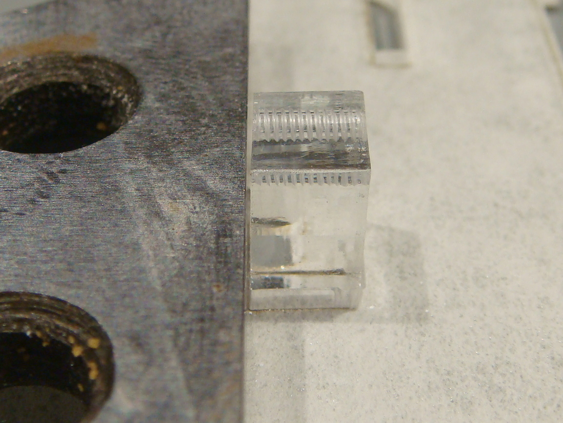
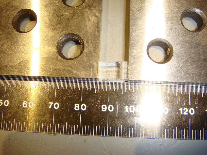
I cut several slots in a flat sheet of thick clear acrylic using the Proofgrade settings, since the material is Proofgrade. I have a corresponding part that slides into the slots with a tight fit to make a T shape. I have checked it for flatness and have several strong magnets on it to keep it flat. I have aligned all my layouts so that any lack of square in the XY direction is all aligned. Then I cut the parts. When I remove the masking and assemble the parts, the crossbar of the T is off of square by about 1-2 degrees.
I have seen this behavior for all Proofgrade materials and all other materials I have used.
Shaving the edges means I have to somehow calculate the angle to adjust the kerf so that I have enough material to shave. Then when I glue it in, the joint is visible since the angle is enough to create a gap at two opposing edges, and now the joint is weak in one direction.
This is not a narrowing of the slot due to kerf width changes. It is a tilt of the slot normal to the face of the material. I am aware that the laser isn’t a vertical cylinder but two cones stacked on their points with the focal point being the joint between the cones. Even with this geometry, if the beam centerline was square normal to the surface being cut, the slot would be straight and the parts would fit square. The beam is clearly passing through the material at a slight angle.
Increase power/decrease speed = the vaporized material (smoke) absorbs energy, so relatively less reaches the bottom of the cut, making for a V shaped kerf. Adding more energy (either more power, or slower travel) can help overcome that on deep cuts.
However, are you saying your kerf is slant shaped, rather than V shaped (so that the offset is in only one direction, so / rather than V?) If so, then something wacky is going on, like the beam not being at the center of the lens.
Yes, I am saying that the kerf is slanted.
Yes, yes, it is. The laser is focused from something like a 5mm beam to a focal point typically somewhere near the top of the material. It then expands outward from that focal point to make an hourglass shape. Typically cuts a V into the material making two slanted surfaces. That’s normal.
If, however both sides of the cut slant the same way and are parallel rather than a V then your laser head isn’t flat to the material (or vice versa) or the mirror inside is off kilter.
1 Like
I understand that the kerf sides are not parallel, that the kerf is V shaped. My understanding is that the V should be centered on the beam path. The V on my GF leans to one side.
My problem is not that the kerf is V shaped. I can account for this in my design. What I cannot account for is that the beam is not parallel to the surface normal. The beam centerline is angled relative to the surface of the material. For any type of tab in slot T joint this causes the tab to lean to one side, which causes alignment issues.
If this is normal, I will have to come up with a work around, or return the unit as there is a problem with it and I can’t use it in this state. If it is not normal, I would like Glowforge to let me know how to fix it.
I’m still confused. It sounds like you’ve got it figured out, so support may be able to help you. A tilted beam angle would generally mean something wrong with the machine.
The thing that’s hard for me to understand though is how a slant from the beam hourglass is easier to account for in the design than that of a tilted beam. It seems like if you need right angles, either way it isn’t going to work.
It’s ok though, no need for me to understand of course. But I am curious, so I’m interested to see what support decides or needs to see.
2 Likes
I know what the problem is, but not if it is normal - i.e., within expected tolerances.
When the beam is parallel normal to the surface, the resulting cuts are consistent and the slot sides, while not flat, are average parallel. This means the tab going into the slot will be square to the part that the slot is in. I can account for the lack of flatness in adjusting for kerf and the tiny amount of space caused by the hourglass is just about enough for the glue to wick in. I can clamp the parts square if I am worried about precision and they will cure square.
When the beam is tilted, I now have to account for both the hourglass, which if the focal point is at the top surface is actually a V, and the fact that the average wall on the slot is angled to the surface, meaning when I adjust the slot to allow the parts to be square I have a much larger gap between two faces. The gap is larger than the glue will fill, leaving an unslightly and weak joint.
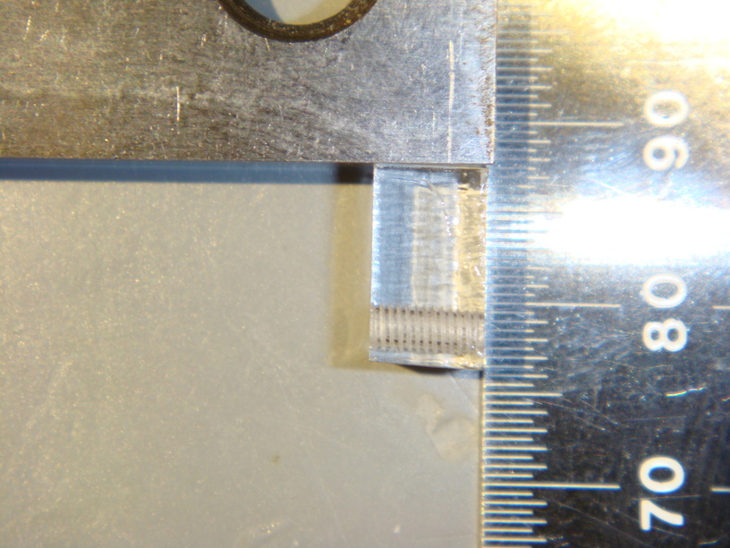
I will see if I can get some pictures to turn out. The ones so far haven’t shown the issue.
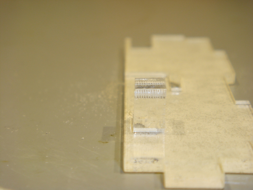
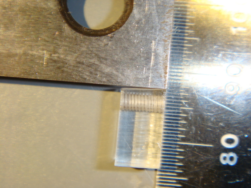
@rita Is there any way someone from GF support can take a look at this issue for me? The pictures show as well as I am able the problem I am seeing. The part is cut from Proofgrade clear thick acrylic and I have checked the sheet for flatness.
My GF is level within 0.2 degrees per my smartphone app, from taking measurements in all four corners.
3 Likes
Where are you setting the focus height?
If you are too high (or too low) then all you will see is the slanted part of the cut rather then an hourglass shape. Can you try making a straight cut in a piece of the same material and show it to us from the edge looking into it?
In other words if the beam axis is Z, the head moves in X, and the gantry moves in Y, place the edge of the material parallel to Y, make a single cut into it along x and then take a picture parallel to X.
That way we can see the cut kerf in context instead of just one side of it.
1 Like
Have you checked that the head is firmly seated on the carriage? Perhaps remove it and check to be certain the surface where the magnets are is clear of any debris? Check that the carriage does not have any vertical play?
Any of those could tilt the head unit. Were those cuts (in the XY plane) parallel to the X or the Y? That could inform you of what might be most important to look at. For example, if the carriage is loose, that would imply that horizontal cuts would have the beam angled slightly toward the rear of the machine. Whereas debris under the head could cause any possible direction of error.
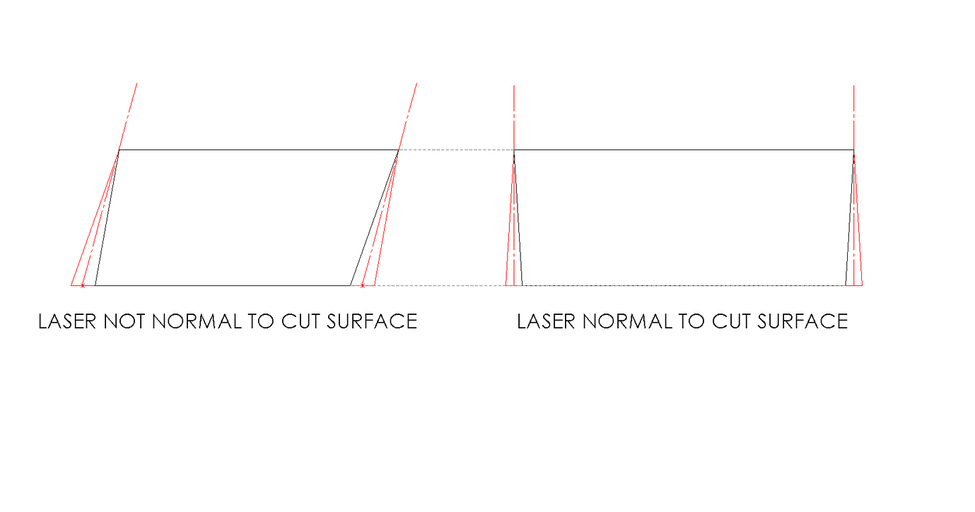
@jkopel This piece is made up of four straight cuts. If it were just the kerf, the slope angle on all sides of the part would be about the same but in opposite directions, with the narrow part of the removed area at the top of the material and the widest part of the cut at the bottom, making the resulting cross-section of the part a trapezoid.
The actual resulting part cross-section is closer to a parallelogram, with opposite sides sloped in the same direction, though a slightly different amount, as expected, since the kerf will change the slope of opposing sides.
@johnse Per my original post; I have reseated the head several times to be certain there are no debris under the print head. I have wiped the holder arm down, I have removed and inspected the print head for foreign objects, and carefully reseated the head to ensure that it is firmly and properly seated.
I was having the same problem. Had to return my original unit,
I have assembled a diagram of what I am seeing with my parts, why I assume the laser is not normal to the material surface. I have seen this with thick Proofgrade acrylic and medium Proofgrade Maple for sure. I have not looked for it with other materials yet. It seems to be only in one direction, but I have not yet been able to determine which direction as I have not done any structured tests.
@Rita @dan I realize you are busy. If you or one of the support technicians can take a look at this, I would like to know if this is within tolerances for the machine or if there is a problem. If there is a problem, I would like to know if it is something that I can repair myself or if I will need to return the Glowforge. Other than this alignment issue I am happy with the laser cutter as it does everything I ask, so I do not want to return it unless I have to.
4 Likes
I liked your post, not because I like what is happening (obviously), but because that drawing is a very clear description of what you’re seeing and that the unit is not behaving properly.
Unfortunately because the expected behavior is to get a cut that is not normal to the surface it’s hard (for me, and I suspect support also) to figure out whether people are describing the expected or an unexpected outcome.
Another one of those cases where taking the time to draw the picture is worth a lot since more words may actually increase confusion.
I suspect you’ll need a replacement laser cutter. Edit to add: But maybe it’s just the mirror in the replaceable head?
1 Like
I’m so sorry for my late response.
I’m looking into what’s happening here and will update the thread when I know more.
Thank you for letting me know. I am happy to provide any additional information upon request.
Right now it looks like most of the misalignment is in the Y axis, as if the support bracket for the print head isn’t perfectly level.
I have checked the crumb tray and the gantry and print head as best I am able with my phone, using a level app, and they all seem to have about the same tilt.
Thanks for your patience.
Would you mind trying something for me:
- Create a design of a 1" circle.
- Print the circle on a scrap of Thick Clear Acrylic.
- When the print is finished, keeping both pieces in the bed, rotate the circle clockwise in the hole. Are you able to rotate it all the way around?
Please let me know how it goes and send me photos of the pieces (both the circle in the hole and the edges of the circle)!