Most of the time I can get the Passthu to work its magic.
So this post is about finding some Clever ways to line up when the magic pass thru does not work.
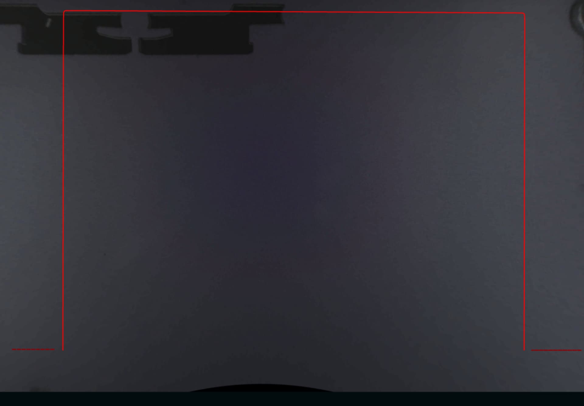
This is the top of the Square Rectangle that needs to be joined with the bottom part .
The vertical lines is how I try to line up the top with the bottom , without scarring the part that cannot pass thru because its to thick .
the red line is the cut line and horizontal line is so I can see if the cut line will line up with the bottom part of the square which you cannot see . , If I try anything else I ruin the Rectangle board I am making by getting to close to the vertical cut line on 2 % power so i can see it.
All this trouble to just get a Few more inches in length on my Rectangle Cuts.
I have pointed out several times the technique I used before the passthrough thing existed and I still prefer. The right hand rail is a reliable “X” and rotation location that leaves only the “Y” direction a variable. If Y=10.9 is marked on your rail then that is repeatable as well. Otherwise, Set Focus particularly in that far corner will align everything there. The other need is to make the top and bottom different colors so you can cut one without cutting the other. Thus you can pick the break points even if not on the same “Y” value, but where they would be the least obtrusive (a big advantage over the passthrough widget)
That way by only using the up/down arrows on the design it will keep the “X” value tight. And using the right rail to slide the material the “X” value of the material is held too.
Then using Set Focus or the number system you line up the “Y” numbers and you can get a very accurate result with the advantage that if all your break lines were vertical, even a millimeter overlap will not be noticed.
Im going to read it over 100 more times, and I knew I should have kept up with my algebra with x = y .
honestly it sounds amazing , but Im not sure what you mean when you say rail ?
Do you already have a jig of some kind in place as I am cutting 0.5 material so I am not using the tray if that matters .
If ever there needs to be a video with a Tip Jar im in.
Thank you .
X is the distance side to side and Y the distance front to back (Z is up and down) All usual robotic stuff uses those coordinates that way.
If not using the crumb tray (that has the side rails) you need to build something that will go into both right-side corners, stay out of the way of the gantry, and hold straight the same distance from the side everywhere. (which is what the rails on the crumb tray accomplish)
Ok, so i need to build something like the crumb tray with a rail , that allows for 0.5 material to fit inside , that takes advanatage of the Divits under neath to place in the same spot .
Ok so the perfect Jig using the x an y to match up precisely everytime eaiser said than done because your starting with a sheet of rubber that has to be rough cut to place in the machine and is never the same size starting off until i make it that way.
Instead of that, the very front and back of the space are much more precise corners that @timjedwards came up with to hold the crumb tray more precisely than those divots. Expanded from that, you could create the entire rectangle or just the front right corner and sides to square against. This works for non-passthrough jigs etc.
However, the Pro passthrough capability starts at the crumb tray level and goes up from there so using the passthrough without the crumb tray gets to silly.