About a month ago, I saw an instructable for a cool clock.
The project features a bunch of 3-d printed parts and some jigsaw work. This is my attempt to convert it to a gforge based project. As a first version, I focused on function, so the overall design is a bit vanilla. The body of the clock is a box from boxes.py with a sheet of veneer on the front.
It is also arduino based and uses the same motors, magnets, balls, and sensors as the linked project. Everything else is an entirely new design including the arduino code.
I had the motors, steel balls, hall-effect sensors, and magnets left over from prior projects, so this was a cheap project to try.
The result is:
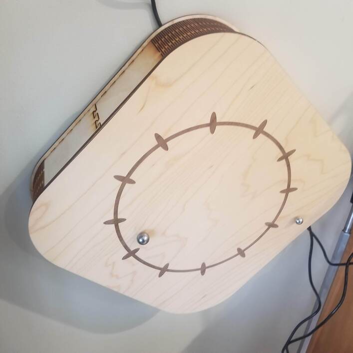
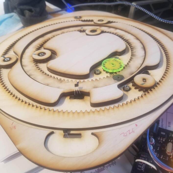
The guts include 2 cheap stepper motors ( not visible in the photo ) driving wooden gears ( on the lower right of the photo, one of them under a yellow cap) to advance the larger gears that have magnets embedded within (one magnet in view at the top of the photo). One big ring for minutes and another for hours. The gears were downloaded from gear generator. Those magnets lay on the underside of the veneer face and move the balls around the clock face to mark the positions the minute and hour hand.
The arduino involved checks a real time clock and advances the hour and minute hands a tiny amount every few seconds. The distance being a prescribed number of steps from the stepper motors. The number of steps is calculated by dividing the total # of steps needed to advance the hand one complete lap by the amount of time between moves. In practice, the minute hand moves 17 steps every 3 seconds. The hour hand moves 17 steps every minute. Why 17? it just works out through the gear reduction in the steppers and the gear ratio between the driving gear and the big ring. I did not calculate this, I simply built it and then measured the number of steps in a lap and found the smallest increment for each. The hall effect sensors and magnets are refreshingly repeatable. 20400 clicks per hour on the minute hand. 12240 clicks per 12 hours on the hour hand.
This type of motor is cheap ( <$3 a pop with driver board) and prone to missing steps. There is no feedback when this happens. So, blindly driving this as described above will not make for a good clock. The solution is to keep the hands accurate by using a pair of hall effect sensors (i.e. a very simple switch that is triggered by the magnets as they pass). These are seen in the photo above as the tiny black objects with 3 silver legs in the bottom center of the image.
When the magnet gets close to the sensor, the sensor acts like a push button. The arduino calculates the difference between the location of the sensor and the actual time of day and adjusts the positions of the hands to be where they should be for that time of day. If no drift has happened, there is no need for adjustment. If there has been some drift, this fixes it. Thus far ( running on and off for a week or so), the minute hand has been off by no more than 3 minutes, the hour hand has not had any noticeable drift.
With that in place there is only the matter of getting the clock started in the first place. There it simply advances the drive until the magnet finds the switch and then advances the drive for each hand to show the correct time.
There are a lot of things i would do differently but I am happy that the first attempt worked with only a bit of hair pulling and a few dabs of grease. More photos and videos here. Note: many of the videos have the clock upside down and in some the rings are moving backwards. Thusly does one also document their early false steps.