Okay, believe it or not, I watched the whole thing. It was quite interesting how our approaches differ. I normally do bottom up design for boxes and stuff but I thought it would be easier to do this top down. I don’t know as I have not tried it. After watching and thinking about it I think your bottom up is better.
2 Likes
thanks. going to do some practicing. I need to be patient
yes I would love to see the video. I like the shape a lot. Thanks for this. please let me know when you make your video. I want to watch
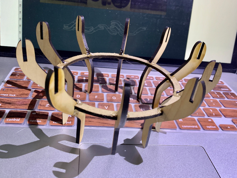
Simplest method to me to create something like this would be to create a 2 circles for the top/bottom, put in x amount of notches at equal distances apart based on your material width/depth and then create the same amount of crescent moon shaped pieces (fins?). Add in the notches/slotting bits to the top and bottom of each crescent before duplicating (so each is the exact same) and then once they are all cut, you just slide them into place.
1 Like
Scroll up a little bit. I posted the video yesterday. Sorry it’s a little long but I hope it helps explain the (a) process.
It’s interesting to look at different ways to accomplish the same result. I considered that, or starting with an oval instead of a “fin”, etc. No clue how a professional would do this, but the learning experience is most of the value for me.
2 Likes
I made this adapter:
like this:
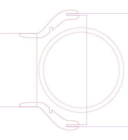
The left rectangle is the profile of the duct, the right is the inlet of the fan. Measure and draw - in your case, just make up what you think will look right. I drew the critical pieces - the “claw” around the fan outlet, and the inside of the duct, then just drew shapes to join them up. I put a notch inside for support. Copied and flipped the part, and created a ring that would slot into the notch.
In your case, draw your desired shape for the segments, notch them for where you want the hubs.
Again, took longer to type than it would to actually do…
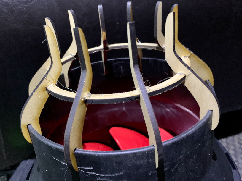
Snapped onto the fan:
3 Likes
Ok, I’ll play, if only because my design tools and approach are different from what’s been presented so far.
I use OpenSCAD for the bulk of my 2D and 3D design work. This excellent, free, open-source package is geared toward programming/math types, and you specify your drawing by writing a text script in one window that is evaluated to generate a 2D shape (SVG file) or 3D volume (STL file).
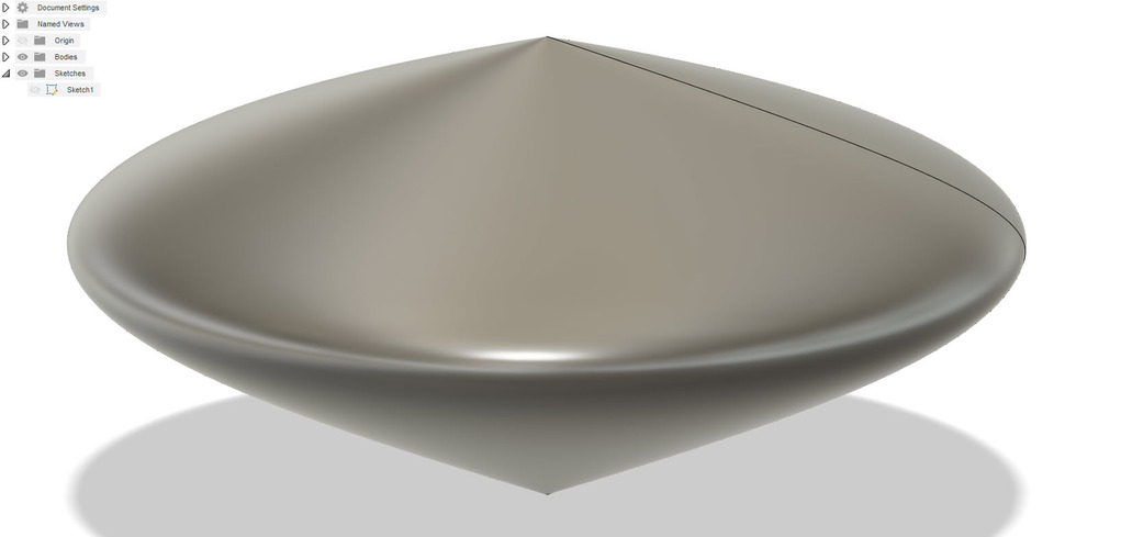
This lampshade is composed of two easily visualized parts, so I simply created a ring with evenly-spaced slots around its perimeter, and a separate crescent shape. (I am approximating the shapes I see in the photo you provided, and my result here is a rough first pass. I would likely tweak a design like this for hours until I was satisfied with the overall aesthetics. My lamp is admittedly kind of ugly.)
In the OpenSCAD script, I can parameterize any important dimensions, so I usually create global parameters to represent the material thickness, which you need to know to cut the slots.
I formed the crescent by taking the difference of a pair of offset circles, then squashing it vertically to 70% of its original height. I then subtracted out the upper and lower notches where these will slot into the support rings.
inch = 25.4;  // define millimeters per inch

ring_od = 3.5 * inch;
ring_id = 2.5 * inch;

crescent_od = 15 * inch;
crescent_id = 16 * inch;
crescent_offset = 3 * inch;

fin_count = 12;  // Number of fins desired around the lampshade
thick = 3;   // 3mm material is ~ 1/8"
notch_depth = 0.25 * inch;

module ring()
{
    difference()
    {
        circle(d = ring_od);
        circle(d = ring_id);

        for (n=[1:fin_count])
        {
            rotate([0,0,n*360/fin_count])
            translate([0,(ring_od/2)-notch_depth])
            square([thick, notch_depth]);
        }
    }
}

module crescent()
{
    scale([1,0.7])
    difference()
    {
        circle(d = crescent_od);

        translate([-crescent_offset, 0])
        circle(d = crescent_id);

        translate([0,(crescent_od/2) - (4*thick)])
        square([(ring_od/2)-notch_depth, thick]);

        translate([0,-((crescent_od/2) - (4*thick))])
        square([(ring_od/2)-notch_depth, thick]);
    }
}


Because this is a relatively simple design, I would usually just export my 2D shapes to SVG files at this point and cut a prototype. But sometimes it is useful to create an assembled view of the parts, to see how the final object will look. This can also be used to perform intersection tests, to catch interference problems between parts in the final assembly.
To do this, I take the 2D ring and crescent parts and extrude them to the material thickness, then translate and rotate the parts into their positions in the final model.
module ring_3d()
{
    linear_extrude(height=thick)
    ring();
}
module crescent_3d()
{
    linear_extrude(height=thick)
    crescent();
}

module lamp_assembly()
{
    translate([0, 0, 0.7*((crescent_od/2) - (4*thick))])
    ring_3d();

    translate([0, 0, -0.7*((crescent_od/2) - (4*thick))])
    ring_3d();

    for (n=[1:fin_count])
    {
        rotate([0,0,n*360/fin_count])

        rotate([90, 0, 0])
        crescent_3d();
    }
}

color("brown")
lamp_assembly();
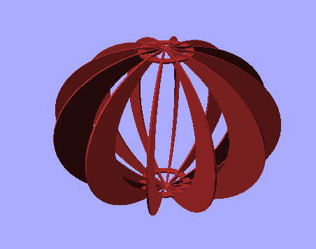
To really test the fit, I might go as far as to model the lightbulb and electrical fixture.
If I were designing a part with a lot of interconnected parts, I sometimes do this process inside-out, using the assembled parts to subtract from each other, to define perfect cutouts.
One last tip: Remember when you design your shade to make sure you have enough clearance to change the bulb someday.
EDIT: I did this very quickly (about an hour to design the parts and do this write-up) and so naturally I made a mistake. I cut the slots in the crescent to be as wide as the material thickness, but then I scaled the crescent vertically by 70% to get the slightly bowed shape. This made the slots 70% as tall as they need to be. I would have caught this mistake if I had done proper intersection testing in my model.
Live and learn!
4 Likes
This topic was automatically closed 30 days after the last reply. New replies are no longer allowed.