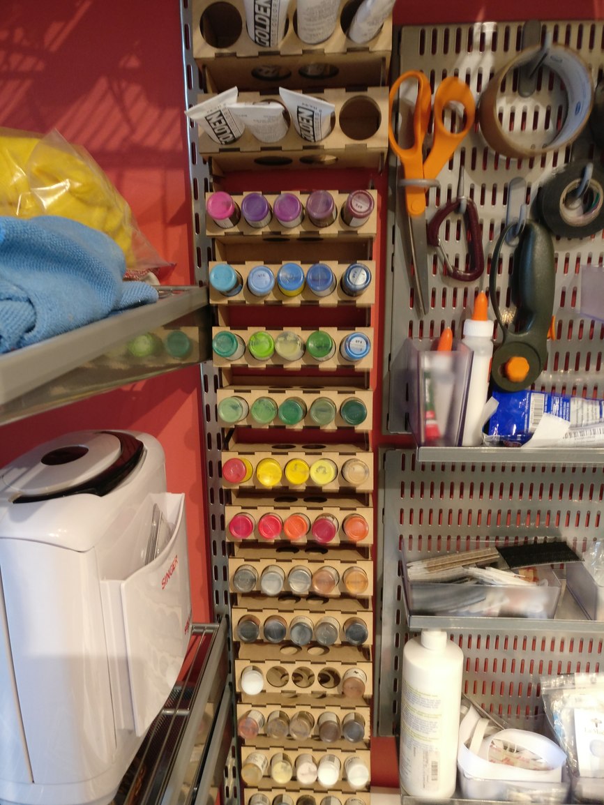
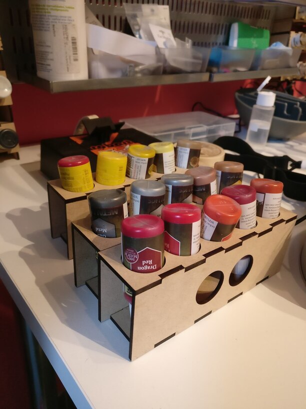
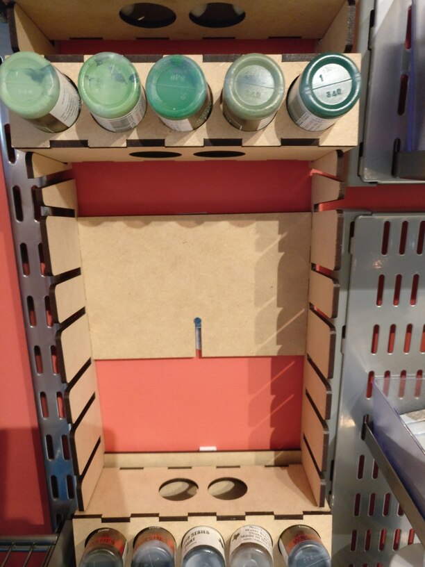
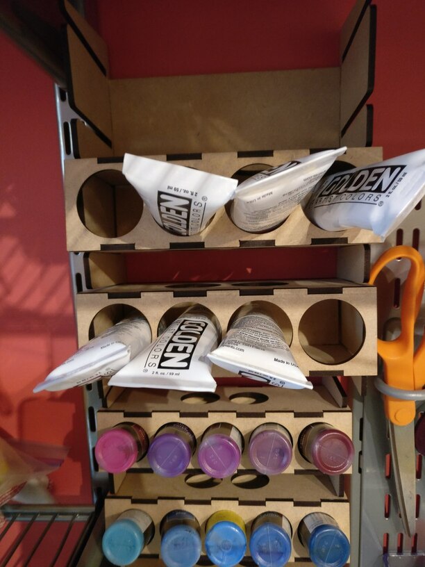
I have a bunch of miniature paints, but only a narrow slice of wall to store them. So I made a paint holder, and decided to make each row a tray that can pull out (in case I need a lot of similar colors, or the paints I need are too high up on the wall to reach while sitting down).
The whole thing was done with medium draftboard, and I used Sobo craft glue to stick things together (it was nearly friction-fit, but I wanted to make sure these were solid). Overall, works pretty well; and when I get more paints, I can just print up another rack and stick it to the wall somewhere.
I hadn’t thought of using OpenSCAD for the engraver. I use it for 3D printing. I guess you just stick to the 2D functions? It would be great to tap into an existing skill instead of learning yet another tool.
Actually, I do full 3D modeling, but work in sheets/faces that are the pieces of wood, and then flatten it to export to SVG. I’m currently using a library that helps generate the cuttable shapes, but I’ve also been writing my own further wrapper to make it easier to generate boxes/trays.
OpenSCAD generates SVG’s nicely - you can model in 3d, then take slices through the model parts and write them out as SVG. The only issues I have are (1) the SVGs are monochrome so if you want to do more than one of cut/score/engrave you have to edit in a tool like Illustrator, and (2) you can only output one SVG at a time, so if you want to generate a bunch of parts you need to write a little code to lay the parts out flat, then export the SVG. Or do each part one at a time.
That is really good to know. I haven’t played with SVG export from OpenSCAD. I like that. That means I can take my fractal models and just cut the middle from them and they are engraver ready!
I don’t mind importing into Inkscape and making adjustments. I usually do that anyway just to make sure the file is what it seems to be.
Yeah, I always do some tweaking in Inkscape afterwards; and I’ve found I need to edit the generated file to indicate the dimensions are mm, because otherwise Inkscape treats it as pixels. So the workflow is a bit ad-hoc, but works pretty well for me.
I’ve run into a similar problem when coming from Fusion 360 .dxf files. After opening in Inkscape, it will NOT allow me to set the display units to anything other than px. The image is the right size, I just can’t visually gauge things as easily. I need to take a good look and see if there’s a setting in Fusion 360 I need to change or if that’s just something I have to live with.
This is what I do for anything I want to model in 3D.
In the svg file I sometimes have to clean up “extra” joined nodes in Inkscape. I think it is a function of the primitive data types OpenSCAD uses and rounding error introduced by rotate and to a lesser extent translate. I started by making pieces in their assembled orientation and then rotating and translating them flat. I’ve switched to making them flat and then rotating and translating them into their assembled positions and this has helped, but hasn’t totally solved the issue. On the plus-side, my node-delete and node-join skills have been improved greatly.