The ripples are not “normal” from my machines but I use cast acrylic from other vendors with paper backing not Inventables stuff with plastic masking. I would report it as a defect.
Thanks. When you say “machines” does that include your PRU as well?
No. Just the K40 and Redsail. I haven’t done any acrylic in the PRU yet. I’ll toss something in tomorrow to check it out.
EDIT: I’m running a job now. I see the striations from the lines (340LPI). I’m running a 4" coaster in 1/8" PG acrylic. The focus height it set for the cut was 0.125" but for the engrave it’s set for 0.197" so it’s defocusing itself. Once this is done I’ll run a test using 1/4" cast acrylic (I don’t have any 1/4" PG acrylic on hand) and report back.
EDIT 2: I had it set to do the cut first and the disk dropped 0.045" below the surface of the rest of the acrylic sheet so it was defocused 0.117". No ripples but I would not have expected the striations especially at the prominence I see. I’m running the 1/4 cast acrylic now and was surprised to see that for 1/4" black PG the settings were not defocused so I kept them - 0.236" for the focus height. The 0.236 is the correct thickness of my 1/4" which measures 0.236 both by my calipers and the manufacturer’s label; not the 0.250" that a “real” quarter inch would be. It’s a nominal measurement. The 1/8" PG clear acrylic calipers out to 0.115" with the masking in place - not the 0.125" that the software chose for the cut height.
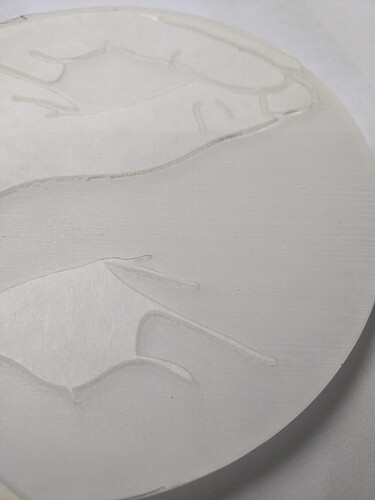
EDIT 3: okay, job is finished and I’m not impressed. Here’s the PG clear:
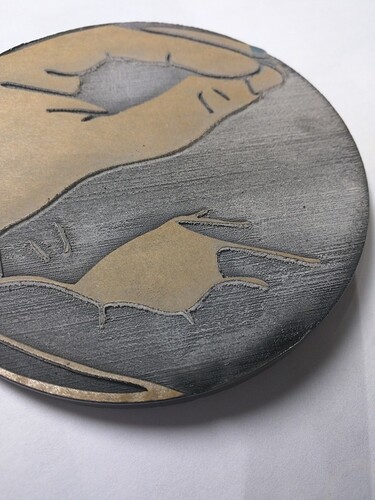
Black:
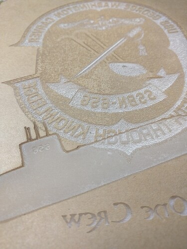
And for a comparison, a reject from a project I did last year.
I expected better - it was doing 340LPI. I’ll do another run tomorrow at 1355LPI but it’s gonna take forever (this one took 22 minutes). I’ll do a full report out. But there’s work to be done.
Looks like the PG sheets are actually metric 3mm and 6mm.
0.115 = ~3mm.
0.197 = ~5mm.
0.236 = ~6mm.
I think what you are calling striations are what I am calling ripples. They are much coarser than the actual LPI. At 340 LPI the line spacing is only 3 thou and I don’t think that would be visible. It is also less than half the size of the spot.
I wonder if they are caused by the air assist. Russ at SarbarMultimedia recommends very low air assist for acrylic, just enough to keep the lens clean. Does the GF throttle back the air assist?
I thought I saw wider gaps/higher ridges in amongst the stripes (striations) in the OP up top. The stripes/striations in mine are actually very consistent ridges & valleys. They look like the layers of a 3D print. They are tangibly thick - fingernail maybe? They are much more pronounced than on my other lasers. See the submarine for example - they’re almost invisible to the eye resulting in more of a frost look.
Right now we have no real control over the settings for engraves except for LPI - we’re running engraves at 1% power and 335in/min. Anything more is overpowered. So LPI becomes a surrogate for power - higher LPI results in deeper engraves. I’ll do a rough calibration tool for engraves to see what effects come of it. I hadn’t bothered because they’ve been making some big changes in engraving - they had a 1 day release of software a month back that had much finer control over power. That may be what’s causing this - overpowered passes where the overlap is double or triple burning and causing the valleys.
In @cynd11’s test the 195 LPI defocused seems the flattest by far and even focused it is better than both higher and lower LPIs. Lower LPI ones that are focused you can see the actual raster lines as to be expected. Bit higher LPI ones get worse ripples that are lower frequency than even the 75LPI raster lines.
195 LPI is the first one where the focused kerf overlaps and the raster lines disappear leaving ripples. So the ripples seem worse when there is excessive overlap but I don’t see why that alone would cause valleys even if it is overpowered. To get that I think either the line spacing is not regular or the power or focus or speed varies from line to line. I would love to see the stepper and beam current waveforms on a scope and a dial gauge against the gantry.
On your examples the lines go a long way across so I don’t think it is a chaotic physical process.
It is very easy to get uneven microsteps with common stepper driver chips, see http://hydraraptor.blogspot.co.uk/2012/04/stepstuck.html. And with the heavy Y axis only moving a few microsteps between lines stick / slip friction could be an issue. When you move one microstep the torque generated by displacement is very low compared to the holding torque. If it is below the static friction of the system it won’t move. Then if you move another microstep the torque doubles and so on until it exceeds the friction and the axis starts moving. It continues to move until the torque drops below the dynamic friction. So to be able to engrave at microstep resolution with open loop steppers the motor holding torque needs to be significantly more than the number of microsteps times the static friction.
This could explain why it gets worse at higher LPIs.
The @cynd11’s text looks pretty good apart from all the loops are filled in. How was that generated / engraved?
The loops look filled in because I didn’t bother to remove the masking–that’s masking you are seeing, not engraving.
I don’t remember exactly what settings I used for the text engrave, I think it was either 195 or 225LPI, power 1%, speed 335, focus height 0.125". The text was generated in Illustrator then converted to outlines, and was done by vector engrave, no stroke.
One thing I just noticed is that there seem to be common ripples between the 195 LPI focused and non focused circles. Am I correct in assuming these were engraved separately, i.e. not in the same horizontal sweep?
Each circle was engraved separately, starting with the one in the top left, down to the bottom, then the one in the top right, down to the bottom. These were vector, not raster, engraves.
I assume you mean they were engraves of vector circles. If they are made from horizontal lines that is a raster engrave by my book. A vector engraved circle would score around the circumference.
I did as @cynd11 suggested last night and removed the remnants inside a PG engrave with duct tape…the horizontal “ridges and ripples” do go away. (Apparently they do just consist of bits of leftover masking and melted adhesive…huh! Larnt me somethin’! Thanks @cynd11 ! )
The actual pattern remaining in the Proofgrade acrylic appears to be a cross-hatched pattern when held up to the light, which I wasn’t expecting.
Go figure!
I don’t understand that. I have a half dozen that I’m doing to test at various LPI settings including multiple passes. The ridges in mine definitely do not go away and are not just masking remnants. They are ridges with valleys I can slide my fingernail into. They didn’t dissolve with acetone last night so now I’m trying to see if flooding with paint will give me a smooth surface.
What did you do? Can you pop the SVGs so I can see what my issue is? I’m engraving a vector (not bitmap) fill.
From your write up - looks like the main difference might be the focal point…I’ve got the focal point for the beam hitting exactly on the top of the acrylic, as measured with calipers.
Also, this does have a “texture”, it is something you can feel - it’s just not something that is visibly noticeable once you remove the lines of leftover “white junk” that looks like adhesive slag to me.
I pressed the duct tape into the engraved area with the back of a toothpick and rubbed really hard - otherwise it is pretty hard to lift.
I had it set at the exact thickness (via calipers) for my latest tests (.236" for nominal quarter inch material). I was trying to get a baseline to then see what effects defocusing would have.
This is way more pronounced than my other lasers. But I have more control over power on those so not sure if that’s an issue. But that doesn’t explain why yours seems to work and mine doesn’t.
Different models? We’ve all got different stuff in our machines at this point…I don’t know what’s in this one, or which tube…it might have one of the juiced ones. (Which bodes very well for the Pro models ultimately not seeing this problem.)
Are you using the default settings, or having to reset every time for Manual cuts? (I have to reset or I fry the bejeezus out of everything.)
Has anyone continued this defocus/polish work on their production unit? If you’ve figured out some good settings, can you make a new post? Thanks in advance. 
Yeah, the retesting is an ongoing thing on all the materials since the Lower power engraves upload and the new default settings.  (Haven’t been writing it down though.)
Just ran a defocused Score on a project to widen the kerf for a decorative element. (It’s not much, but it’s a bit better than the skinny line.)
Pretty sure you can just clean up the acrylic ridges by dropping a little acetone or denatured alcohol (can’t remember which it is now but there’s a writeup on it somewhere) in there and swirling around, or by doing a second defocused pass. @takitus would be the one to ask about the defocusing and @mpipes would be the one to ask about the flooding technique. (Thought I had that one in the Matrix, but I don’t and I can’t find it now. Really great results though.)
Here’s a link to the solvent flood technique:
Oh good! (I’m going to go put that in there now, before I forget again.) 
You don’t defocus a little for that, you defocus a lot - like make it 0.500" ![]()


