Yes.
I’m not seeing a specific experiment outlined in your reply, so I’m not sure exactly what you want me to test. If you do come up with an experimental protocol, keep in mind that I do not own really good calipers, mine are the “cheap” kind.
Yes.
I’m not seeing a specific experiment outlined in your reply, so I’m not sure exactly what you want me to test. If you do come up with an experimental protocol, keep in mind that I do not own really good calipers, mine are the “cheap” kind.
Yes I was waiting to see if GF already does some defocusing at low LPI but you indicate that it doesn’t.
There is a limit to how wide you can make the beam simply by lying about the material thickness because you only have ~ 0.5" minus your sheet thickness of focal range to play with. And very wide beams have much less power density, so you would need big changes to power and speed to compensate. So some of the very low LPIs are out.
So how about trying 75LPI which gives an additional height of 0.19". That is quite extreme and gives a spot size 11 times the area of the normal one, so you would need to increase the power / speed ratio by 11 to get the same depth.
The easiest material to test it with would be 3mm acrylic I think. With wood you get ridges due to the grain.
Once you get to 270 LPI the focused beam is already more than twice the line spacing, so I would expect lines not to be visible. I that the case? If so defocusing is only needed and practical for 75, 125, 195 and 225.
Tests of a simple circle raster engraved in thin acrylic at those resolutions with and without defocusing would be interesting but I would test the hypothesis that lines disappear at 270LPI with no defocusing first. If they don’t then I would go up in LPI at normal focus to see how much overlap gives a flat result.
The power settings I have available range from 1-100 and the speed ranges from 4-335 inches/min. Normally when engraving the power is set to 1 and speed 335. When you say to adjust the power/speed ratio by 11 times, what would you suggest for power and speed?
If power is linear then it should be simply 11 and keep the speed the same. However I think the current power settings are far from linear. The ones that got rolled out by mistake and then rolled back were probably more linear.
In general, for the fastest job you increase power until you hit the limit and then reduce speed if it isn’t enough. The effect on the material is roughly proportional to power divided by speed. Since we have no way of telling how the power setting is mapped to actual Watts but speed is actual speed it might be better to simply reduce speed by a factor of 11, so about 30 for this experiment, where job time is not a priority.
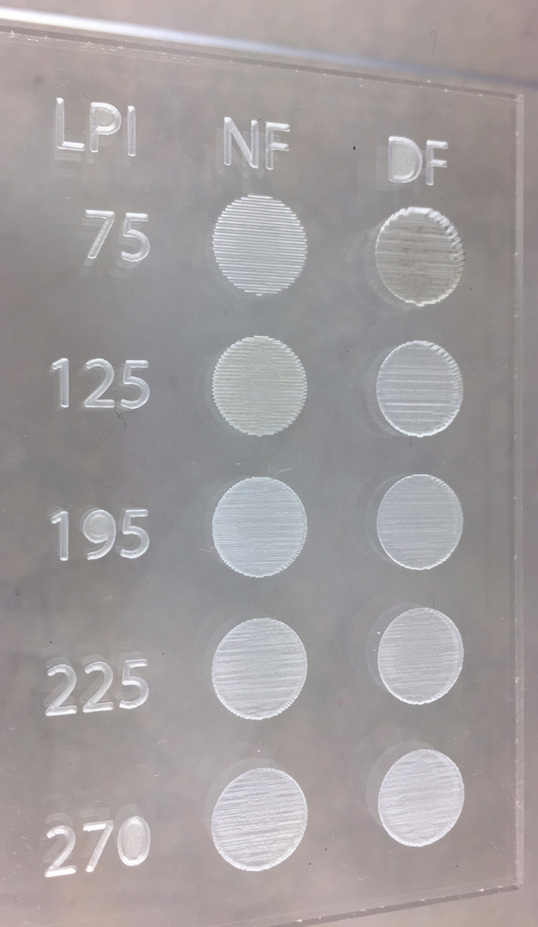
So, to be very clear (to avoid wasting time and material), this is the test matrix you are proposing:
Two columns of circles, four rows. Test conditions of each as follows with numerical values in the order, LPI, Focus Height, Power, Speed:
75,0.125,1,335 75, 0.312,1,30
125,0.125,1,335 125,0.205,1,30
195,0.125,1,335 195,0.147,1,30
225,0.125,1,335 225,0.134,1,30
Column 1 is regular focus, column 2 is defocussed.
I would have thought that you should increase the speed as you get closer to the material at the higher LPI settings. If you have any adjustments to this table before I do the run, please let me know.
The focus numbers are correct assuming your material is exactly 0.125" but you are right that the speed should increase with LPI.
For constant energy density I get 30, 84, 204 and 271. The formula is original speed / (2 / (LPI * 0.008)^2)
I.e. the spot size is increased from 0.008" to 2 / LPI, so its area increases by the square of that, so reducing the speed by that factor gives the same energy density.
Okay I did the test but I need to repeat it with recalculated settings. I based my settings on 0.125" but the actual size of the 1/8" PF acrylic with masking removed is 0.104". Still, I thought you might like to see the image before I do that. Because it seems like the energy density is way too high for the 75LPI one at least. Are we sure about that 11X thing? Not sure exactly where that number came from.
First thanks for taking an interest in this and doing the experiment.
Yes 75 and 125 look to have gone much deeper so they need to be faster. The speed of 11 comes from the fact we are targetting a spot size of 2/75, which is 0.027" that is 3.33 times the nominal spot size and 11 times the area. However since the beam is twice as wide as the line spacing each area gets covered twice, so that is probably why the correction is too much.
195 seems to hit a sweet spot both in the focused and unfocused versions. The odd thing is the higher LPI tests seem to have worse rippling that I can’t explain. It is much coarser than the actually engraving lines, so something else must cause it. The same happens on the lower LPI tests. For example most of the engraving lines disappear in the unfocused 75 LPI but there are some widely spaced ripples.
Maybe there is some behind the scenes magic we are not accounting for. I do know that the default engrave settings for 1/8" PF acrylic are already slightly defocussed considering we are working with 0.104" material (“Light” is 75 LPI at 0.125", “Dark” is 340 LPI at 0.197"). Standard disclaimer–they are still working out settings.
I’d really like to learn how to use defocussing effectively because there are some applications I’d like to try. Maybe there will be expansion of the GFUI that will include more options in that regard.
So, is there any value in repeating the test with numbers based on 0.104"?
And, I just got the Discourse slap on the wrist for replying to you too many times! Apologies to @Xabbess for hijacking her thread–I’m hoping there are others interested in these experiments.
Yes, there is.  I, for one, am keen to try engraving shallow moulds in acrylic, and losing the raster lines is more than academic .
Ignore Discourse, it doesn’t seem to like discourse between two people!
I don’t understand the coarse ripples on any of them, but in particular the normal focus 270. If it was wood it would get blamed on the grain but with a homogeneous material I can’t see any other reason for ripples other than the laser beam fluctuating. I would feed it back to Glowforge support and see what they say.
Support is not real big on answering questions. So wouldn’t expect an analysis or explanation. Occassionally, but not the norm. Usually you send a problem report and they say thanks, will investigate.
Oh great, so even when you get a machine they wont answer questions. If they don’t change their ways I will have to cancel.
These are pre-release machines. Information flow is only intended to help the company understand issues. Never any intent to hold the user’s hand. Would expect the focus to be customer centric with production machines.
Yes but they should be able to say whether ripples are to be expected when engraving acrylic and if so why.
Absolutely. I never expect to hear back when I submit a report, I know the info will be forwarded to the folks working on those issues.
Guys, I suggest we start a new posting about defocussing if there is more to say on the subject. I think we have hijacked this thread for long enough.
So I’m thinking the argument about overlap holds in a more general way. Even when (slightly) defocused you’re depositing all of that energy in a relatively small area, and the part of it that doesn’t destroy material is going to propagate out slowly from where it was deposited. Additional nearby energy deposits will add to the original in a weird time-dependent way. Meanwhile at least two other interesting things are happening: One is that material ablation isn’t strictly a function of energy deposited because there are work functions that have to be overcome to do any damage at all, blah blah, and the other is that the beam is not nearly uniform across the spot, so “illumination within R=whatever and none outside” is questionable even with perfectly focused. And at anything over 125 lpi you are going over the same area multiple times, running the risk of interesting aliasing artifacts (much like the sub-harmonics you get when sampling high-frequency signals at too low a frequency.)
Thinking about this some more: perhaps there is no need to change the speed. The same amount of energy is going into the total area of the circular engrave regardless of focus.
An interesting test would be to do two circles side by side with the same settings so that they are engraved in the same horizontal sweeps and see of the ripples are aligned. If they are it implies they are generated by the machine. If they are random then more likely some chaotic physical phenomenon. Perhaps the air flow over the molten material forms waves like wind over a desert forms dunes.
I am struggling to see where the odd LPI numbers come from. I can get 1355 and 75 if I assume metric GT2 belts and 30 tooth pulleys, x 16 microstepping. However the others come out at 677, 452, 339, 271, 226, 194, 123.
30 tooth GT2 pulleys would be an odd choice though as they don’t give nice steps in metric or imperial units. 32 teeth would give exact metric units and MXL belts would give exact imperial units.
Not really.
One reason they want the PRU folks to be reporting absolutely anything is to gauge what a user EXPECTS. So, if you report ripples… that implies you expected not-ripples. And thus, they will add “Try to get rid of ripples” to the hopper. Come ship time, they will THEN say if ripples are “intended” or not, based on being able to remove them or not.
At this stage… nothing is intended, other than users are happy with absolutely everything.
Well if Glowforge wont say if ripples are to be expected or not does anybody here with a laser cutter from another company know if the acrylic engraving looks normal or not?