I can’t really tell from the cropped screenshot, and I’m not an Affinity Designer expert, but it looks like what you’ve got there is a single thick stroke. The Glowforge software doesn’t pay attention to stroke thickness, so what you need to do in that situation is to convert it to two strokes with a fill in between. That function is usually called something like “expand stroke” or “outline stroke” or something along those lines. I’m writing this on a train so I can’t actually run the software to look at it. But if you can find where to do that, I think it may address your issue
Yeah, I’d have to see the SVG to offer an opinion, but I suspect the inner circle of the O is its own object, rather than being “subtracted” (Inkscape term) from the outer perimeter.
Ohh… the O. I misread the original question. I thought the whole rounded-rectangle thing was being filled. If it’s just the letter O, well… it’s even harder to tell what’s going on here. It doesn’t seem like a particularly proprietary SVG, so maybe sharing the file would be an option? That would help people to diagnose it. Otherwise, a whole screenshot with the problematic object selected and all of its properties visible would be useful.
The ‘Circle’ is a shape with blue stroke around it. You need to convert that to a path. So where when you select the ‘circle’ only it is selected and there is not ‘three’ lines going thru it.
(The center line is the actual shape, the outer two is the stroke width.)
Aha, yes you did! There it is! Discourse does funky stuff with SVG files…
Anyway, the reason the O is solid is like I said - that you simply have a circle within a circle, as opposed to the inner circle defining a “hole” inside the outer one.
In Inkscape, you would break those apart, then “subtract” the inner circle from the outer one, and be left with the required shape to engrave correctly.
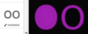
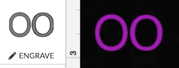
To wrap this up - here’s what two circles look like in the UI when set to engrave, the way your file is on the left, the ‘correct’ way on the right.
In Inkscape, text is automatically converted the ‘correct’ way, I’m sure someone familiar with AD can tell you how to do it. You shouldn’t have to go to every letter and correct them.
Sorry, I’m not sure I understand. In my file isn’t there just a single curve with a stroke around it? I don’t see a second or inner circle. I see one circle and a fill. Is the fill acting like an outer circle? You must be seeing something in the SVG that AD doesn’t show me. Let me try Inkscape…
One thing that sort of fixes it is if I go to AD’s Layer Fill Mode and select Winding (non-zero). I still have an extra oval I need to set to ignore (the one everyone else sees in the SVG but me although I sort of see it in Inkscape, and it looks like the ovals are drawn in opposite directions).
You got it, this is a known issue. Glowforge doesn’t support even-odd winding. If you search “winding rule” on the forum, you’ll find a few years of people being hit by this.
I always forget about it because it doesn’t tend to happen to Illustrator users.
No. Your software is saving it as inner and outer paths.
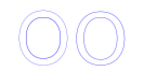
You can’t work with strokes - lines with defined thickness. You have to work with paths, the lines that actually define the “edges” you are looking for. I have no idea how to do that natively in that app, but here are the paths it created in the SVG file you uploaded. just opened without modification in Inkscape.
It’s converting the “edges” of your strokes to paths. That’s fine, but won’t work for text (or other shapes-within-shapes.)
However, as I stated earlier, all you have to do to fix it is break apart the ‘O’, then subtract the inner circle from the outer (it’s the “difference” path boolean operation.)
You will also probably have to also delete the additional path around the border to get the desired results.
Thank you for the great information everybody! @mahboud would you please let us know if the advice you received from the community got you up and printing with your design?
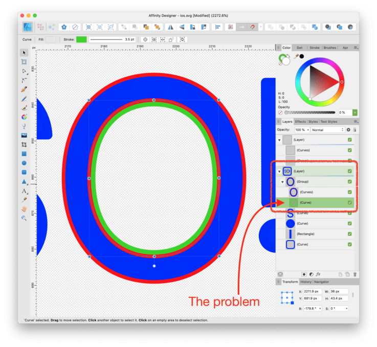
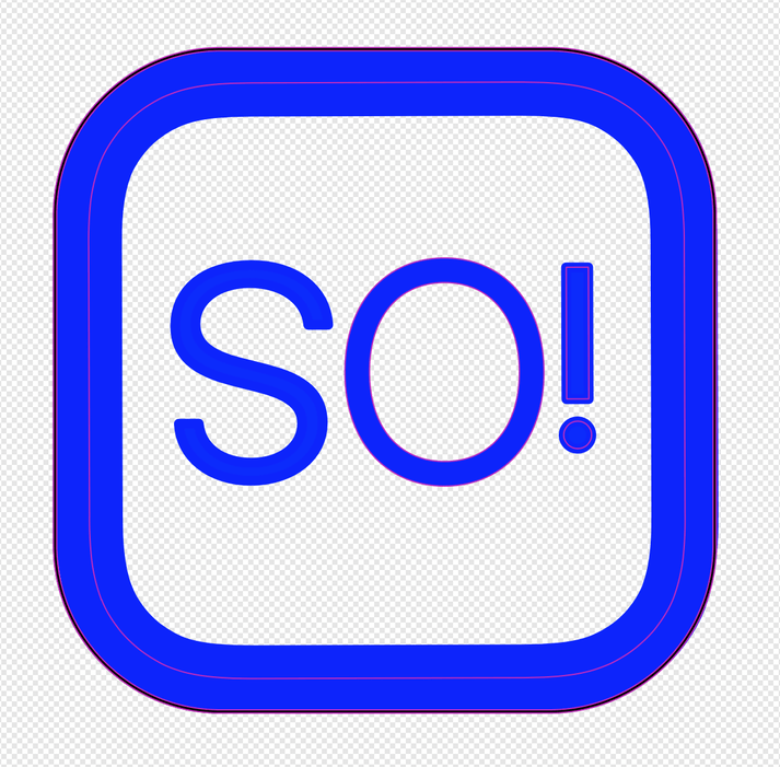
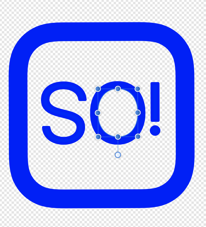
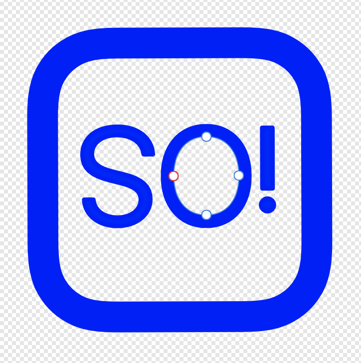
The problem is that you have an extra curve. Take a look at this group containing the “O”. It contains two separate objects. I’ve given each of them a differently colored stroke so you can see them more easily. The compound curve with the red stroke is the one you want. The single curve with the green stroke is extraneous and you should delete it.
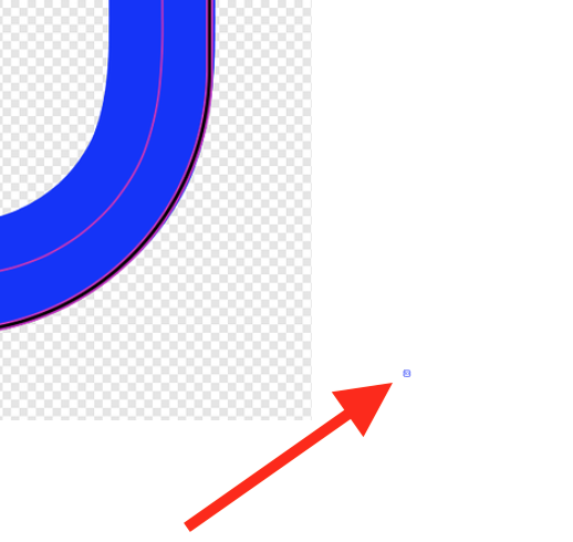
If you look carefully in the Glowforge interface you’ll see that the actual “O” (what I gave a red stroke) and the extra filled area in the middle (what I gave a green stroke) is actually two separate entries in the list of operations on the left:
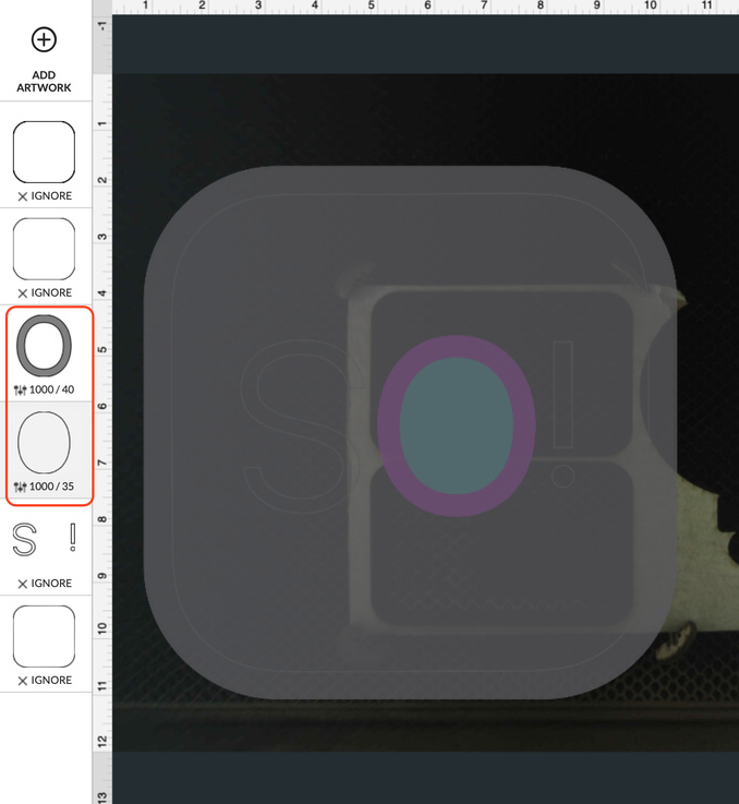
See the two items in the red box on the left? The upper one is the “O” you want. The lower oval is what you want to get rid of. You can either delete it from your SVG or you can just set it to “Ignore” in the Glowforge interface.
While the Glowforge bug with winding rules that @chris1 mentioned is a frequent cause of problems for Affinity Designer users (as well as those who use Corel Draw and many other programs) it doesn’t affect this particular file.
Unrelated: You also have multiple copies of your rounded rectangle outline (which I’m guessing you’re using to cut out this shape. You might want to fix that, too.
Of course it can. I have no idea how this file ended up so messed up.
Hmm. Did you remove the redundant path from the original?
If you did and it still shows up that way then it’s probably a fill rule issue, but I didn’t see any fill rule problem when I tried the original file. (But there are some very weird inconstancies in the Glowforge’s fill rule bug, where sometimes it respects fill rules and sometimes it doesn’t.)
I don’t know if it applies here but there are definitely some bugs in AD’s boolean operations. I have a file with a shape where I can Subtract Front with a square, and it works… but if I put a circle in front, after Subtract Front I have to manually change the winding mode to get it to look as you’d expect. It is very strange.
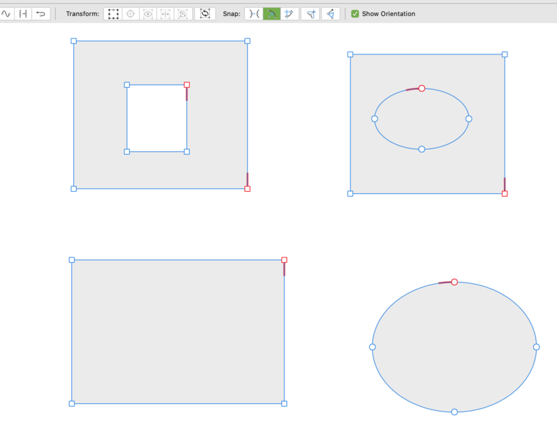
There’s no bug. But it is annoying that by default a shape drawn with the rectangle tool has counter-clockwise winding and the a shape drawing with the oval tool has clockwise winding.
So when you subtract them the results look the same in the Even-Odd fill rule but different with the Non-Zero fill rule. Subtracting shapes flips the orientation of the rear shape and then combines it with the front shape. So if they start out with the same orientation, subtracting them ends up with two shapes of opposite orientation, which does what you expect with the Non-Zero winding rule. If they start out opposite (as a square and circle do by default in AD) then when one gets flipped they end up the same and you get the unwanted fill.
I suppose AD could look at the orientation of the two shapes to decide whether or not to flip one of them, but that gets complicated when the shapes aren’t so simple. (If a curve crosses over itself multiple times so parts of it have one orientation and other parts have the opposite orientation, what should AD do then?)
So there’s no bug; everything works according to the rules. But I do think that all the shape-drawing tools should probably draw things with a consistent orientation.
I highly recommend downloading the AD 1.8.0.5 beta, which (a) provides an option for viewing orientation and (b) makes it easier to reverse just part of a shape. (In previous versions of AD the Reverse Curve button always reverses all curves in a shape, but in AD 1.8.0.5 if you only have only one curve selected in a compound shape then only that one curve will reverse when you click the Reverse Curves button.
Here you can see the new Show Orientation option at work:


 although I sort of see it in Inkscape, and it looks like the ovals are drawn in opposite directions).