Deleted
Deleted
3 Likes
Deleted
4 Likes
I have a couple of ideas.
Didn’t one of our old members who worked on replacement software figure out how to add an ethernet port? I thought some hardware revisions had the pads for it, though no jack was hooked up. Depending on how the OEM OS is set up, it might Just Work if it was hooked up.
I could be misremembering and even if I am not, it would take some serious luck for the port to work even if it was restored. The company would have had to leave support in… seems quite unlikely.
If the wifi chip problem is a solder joint, it may be possible to repair it. You can get heat guns to reflow SMD solder, and it is even possible to bake some boards to fix them.
If it were me I would look up how to bake a board and give that a try – nothing to lose, right?
4 Likes
Good find!
And those pads are nice and fat… an easy soldering job. DOOO IT!
4 Likes
As an engineer and tinkerer, I always cringe when a perfectly good product has to go to the scrapyard for lack of a critical part or timely repair information.
Thanks for sharing your disassembly process for the benefit of increasing our knowledge of the workings of the ![]() .
.
13 Likes
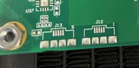
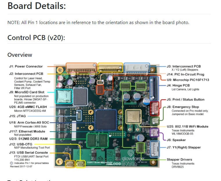
I’m going to assume J12 is the ethernet port, and J13 is the Data port, a tech plugs a laptop into to look at data / software / etc.
2 Likes
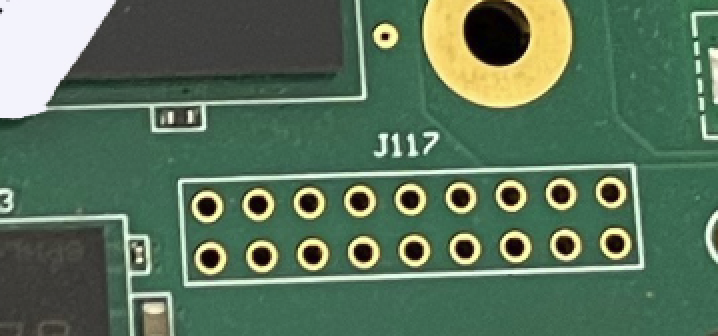
Some old 2017 discussions identify J12 and J13 as USB connectors, and J117 as “ethernet module”.
4 Likes
its interesting you say that The “J12 & 13” graphics are ethernet – not a USB – can you show me J17?
2 Likes
J117 is near the middle of your photo of the board. The discussion linked to something on the Openglow repository but it’s gone now ![]()
1 Like
I found a reference for you that’s still online:
3 Likes
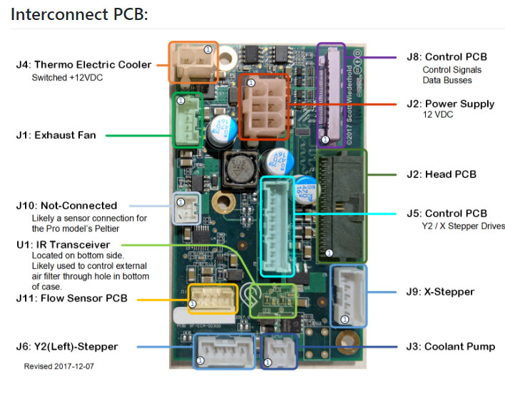
So you have the interconnect diagram from OpenGlow, did you not download the rest of the OpenGlow documents that detail each of the PCBs, their layout, and function?
1 Like
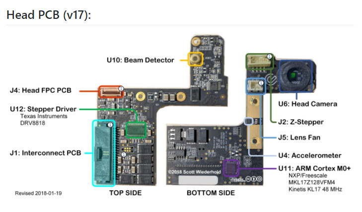
Here is everything I have from Scott’s intrepid teardown (fuzzy pictures). This was an early version, 2017 as noted on the boards, and I have no idea how things may have evolved since.
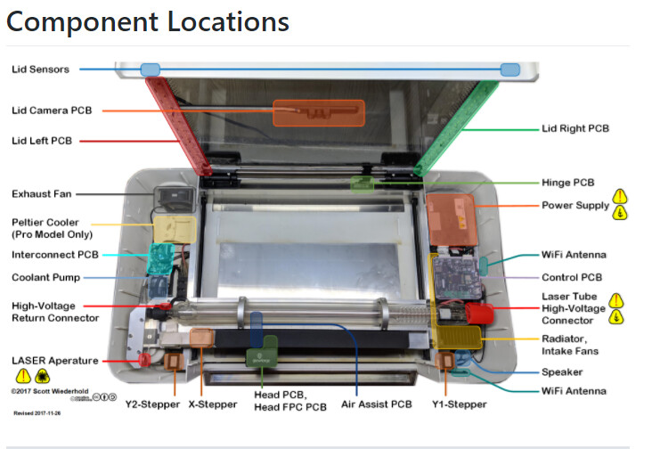
8 Likes
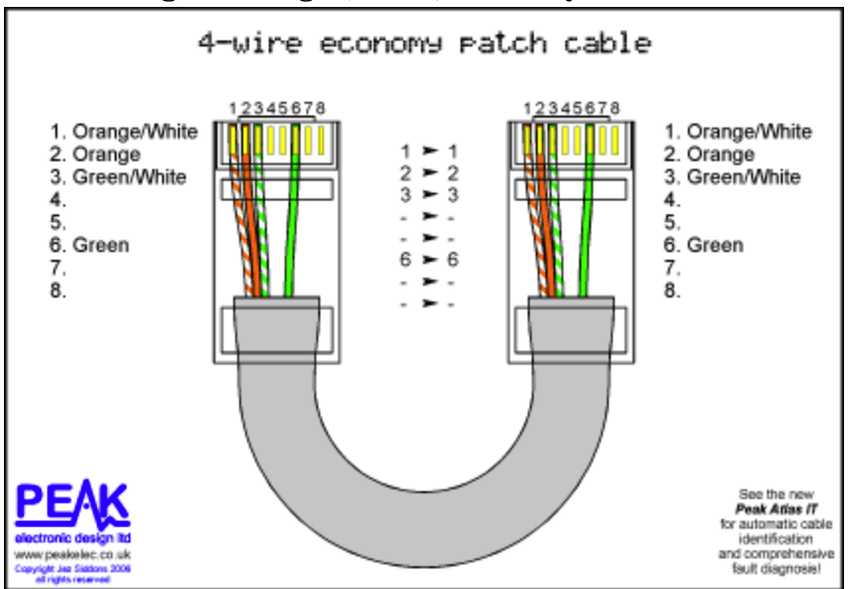
Yeah, those are not the footprint for an RJ45 jack.
The early machines had USB ports installed, and you could (especially with a clever jig) connect to the console and log in. Or so a little bird told me.
At some point, they stopped populating the connector, which made it fairly obvious that the idea that Glowforge was tinkerer-friendly had gone out the window.
8 Likes
Ethernet is 8 pins plus usually two PCB anchors and two ground pins for the shield. The ones you have shown are mini- or micro-USB. I think mini because of the four large retaining pads.
Your ethernet module is more pins because of additional data, power, and ground lines. It’s like a PCI card, not an ethernet port.
3 Likes
@PrintToLaser This is awesome stuff! - I am glad you kept it!
Jonathan
2 Likes
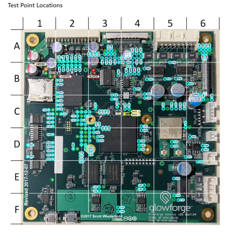
I thought you might find the test points helpful as you eviscerate those machines. Thanks go to Scott.
1 Like
Baked… failed – BUT it was a GREAT suggestion!