AMEN to that!
2 Likes
I’m so delighted to have this as a resource! I’ve learned a few CAD packages over the years but I’ve been eyeing F360…
4 Likes
A question and a comment.
First the question, I see you saved kerf in the parameters but I don’t see it used. Am I missing where it is used or did it not make it into the model?
Okay, another question, could you run us through your workflow? it is obvious that yours is a bit different than mine and if yours works better…
The statement, I am defiantly not an F360 expert but I do think that long term you’ll be happier if you make one body one component. It opens up certain permissions and capabilitys that working in bodys don’t give you.
5 Likes
Kerf is not actually in the model but it is used for calculating the “halfkerf” user parameter which is used to generate the laser paths. It’s a little bit of duplication, the user could just as easily enter half the kerf width into a single parameter, but this way just takes that math step out of it.
Once you have your sizing and material thicknesses adjusted, go into the Drawing workspace and F360 will automatically start a “Base View”. Just click somewhere on the page to position it. From there you can add projected views. You’ll need two “End” views, two “Side” views, and two “Bottom/Top” views to make a complete box. Then on the left side of the screen you’ll see an option tree for each view where you can turn parts of the model on or off. Example, in a “Side View” you want to hide the “End” and “Bottom/Top” bodies so you can isolate just the “Side View”
Setting up the drawing might take you more time, at least at first, than your workflow of projecting sketches and exporting DXF files, but the Drawing is dynamically linked to the Model. If you change the model, the drawing updates. Then you click on the “Output” icon and select the PDF file option and it’s ready for laser or adding artwork in AI, Inkscape, etc. It makes iterations of the design really fast once the grunt stuff is taken care of. I had hoped that the Shared download link could have included the drawing I set up as well but no such luck.
Yeah, I’m new to F360 workflow options. That Component/Body organization thing frustrated me to no end. I’m used to Geomagic Design or Pro-Engineer/Creo where each feature (body) just lives on its own in the timeline, and for something like this box, you would have a separate part file for each face, then a separate file for the assembly of those faces into a box. F360 puts all that into one file, one interface, and it threw me a little bit! LOL.
5 Likes
Thanks for this. It’ll definitely be a big help to me!
1 Like
Inventor (2009 IIR) was this way.
Considering historical prices for a single seat license of an Autodesk product, F360 for free blows me away.
Fusion is very powerful, and I any precieved shortcomings I can easily forgive for the price! ![]()
8 Likes
So from the well you do it in normal material A I will do it in crazy material B posts:
So somebody has got to do something equally funky on the GF…
6 Likes
Yes, it almost makes you wonder what the plan is at the core of it all. Even the commercial subscription cost is peanuts compared to subscriptions of their other software.
3 Likes
Make everybody depend on it, then jack the price 1,000%.
(garsh I hope not)
4 Likes
Seems that establishing it as a go-to because of its power and price could work for them. Popularity in the market is worth a great deal.
2 Likes
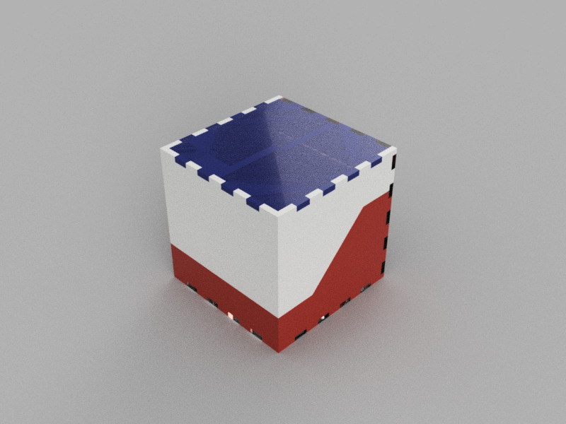
I have an updated version of the model online. This one has a plane that slices right through it to make Top and Bottom “halves” of the box, for those that may want a hinged box top!
This is still fully parametric, by the way. Including the plane that slices the box apart. You can change the angle, size, location of the slice just by editing the dimensions for the sketch, or you can completely change the shape of the sketch if you like, make it curved, zig-zagged, or make it like an interlocking puzzle piece!
This is a new link because the original design is still maintained. http://a360.co/2noMyKF
16 Likes
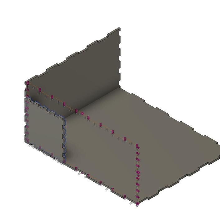
@mpipes, so I downloaded the parametric box and imported it into Fusion. I set my parameters and everything looked great until I checked the Laser_Path. It appears the side wall is not compiling properly. Am I doing something wrong? Everything else seems to be working perfectly.!