"Parametric" design in inkscape

No one:
Evansd2: What’s that?! You want a super long Inkscape hack post? ON IT.

So before I begin: This post in intended for people who are pretty familiar with Inkscape. If you don’t know how to modify nodes/paths, use clones, or rotate a guide, chances are you aren’t the target audience. That’s not to say that there isn’t something for everyone here, but just keep in mind that this isn’t intended as a beginner’s guide, so I will be moving quickly.

My goal: take an older tab-and-slot design of mine and convert it to a more editable form, to allow for cutting with different material thicknesses without scaling the whole model. Using this method will let you make quick and easy wholesale changes to the design without redoing the entire thing. Let’s start.


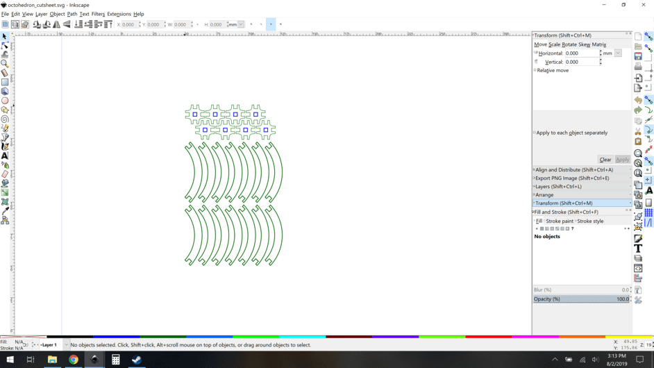
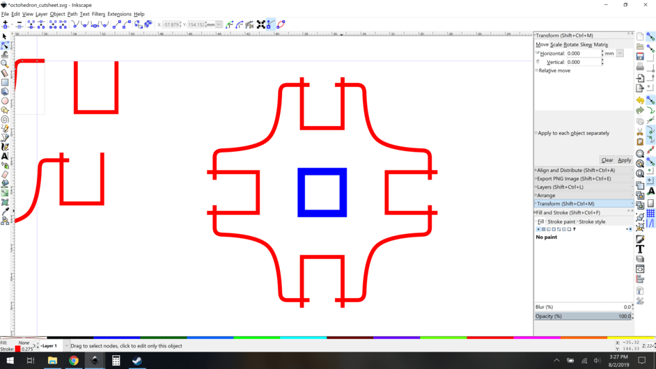
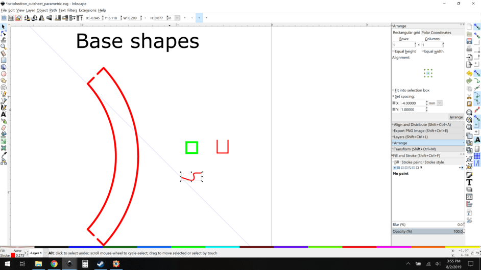
My starting point. This is a basic octahedron model, more on that later. This is a bunch of closed paths, with colors set so that the windows cut first and the shapes second. So far, so normal.

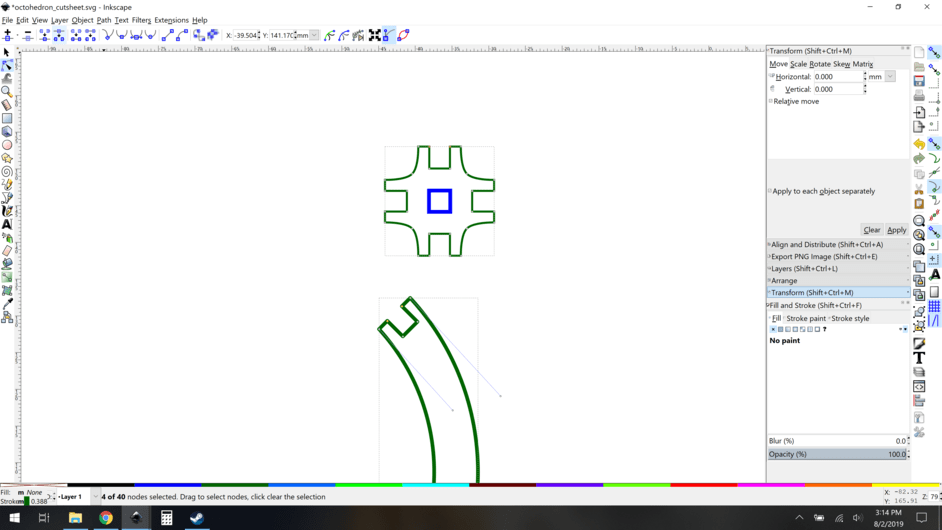
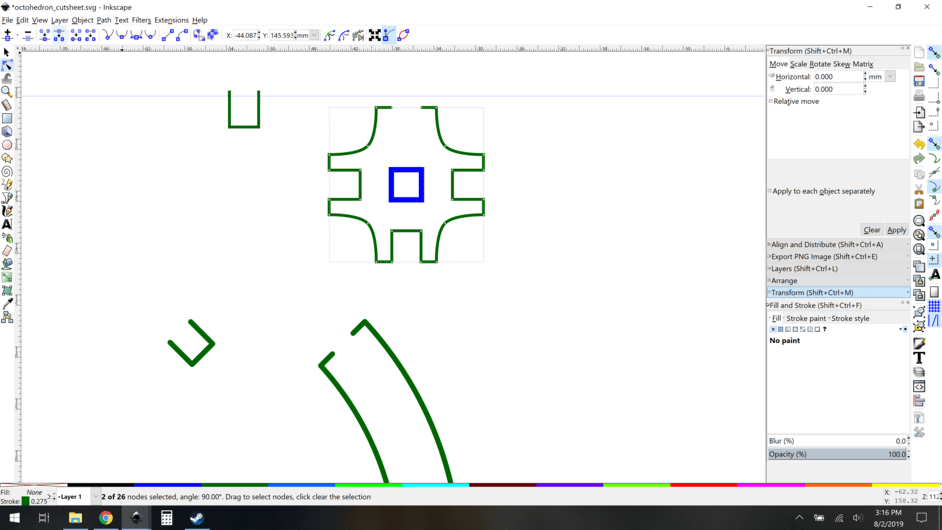
The first thing I do is isolate the notches (slots) by cutting the paths and breaking apart. Select the relevant nodes (highlighted yellow) and click the node breaker button (highlighted upper left) to break those paths.

Broken. Good.

I like to add a node to the bottom of the notch, this allows for easy alignment later.

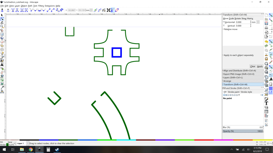
Now I also like to extend the “depth” of the notches, this ensures that the cuts will always be clean at the junctions. I also want to keep nodes at the correct position of the real depth, so I add nodes and extend the sides. (the guide is the original height. Not pictured: adding nodes at the guide height, but we did say you were an advanced inkscape user…) Now you have taller notches than you need.

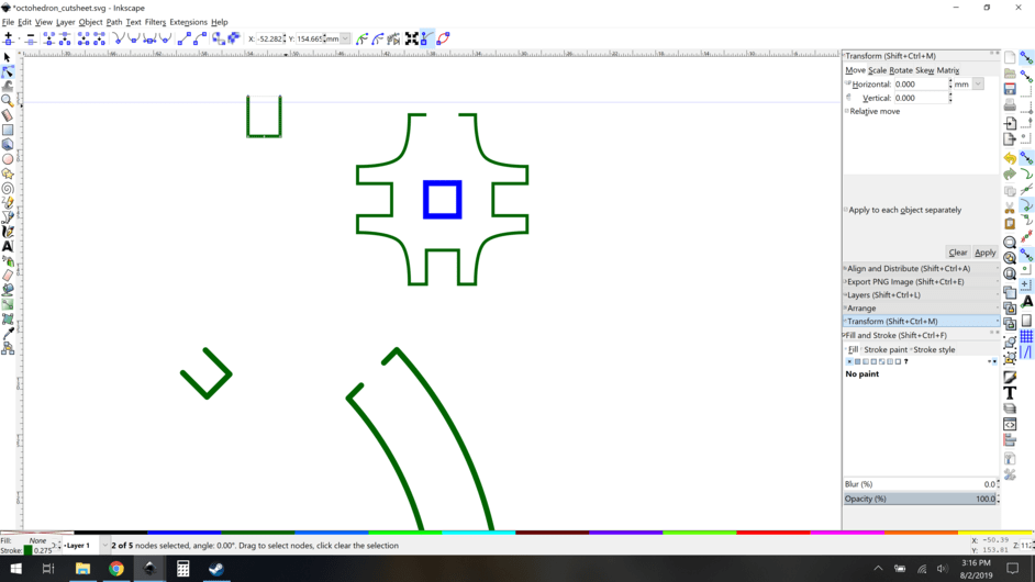
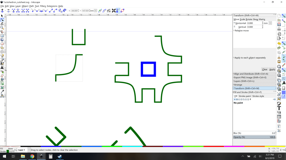
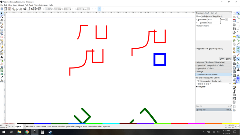
Now I want to break off the “corners” of the original piece, they’re going to be parametric too. Again, we break the path here (highlighted node on left)

Break it apart and pull it aside.

Notice that I have a center node, I break that apart, because really I want this to be a symmetric piece. This will be obvious why later, but for now trust me. I also change the color of the new smaller paths to make it easier to see which are which. Then, after I do that, I make clones and set them below the originals.

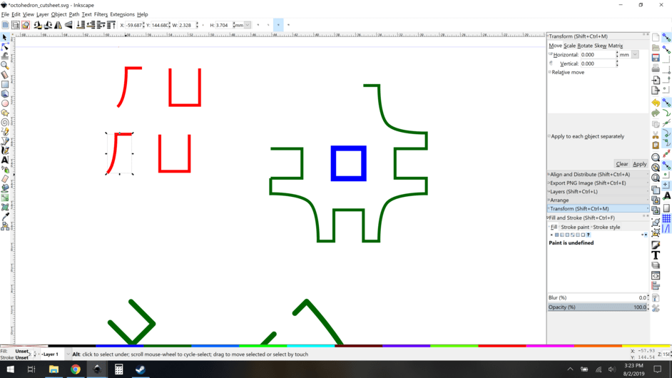
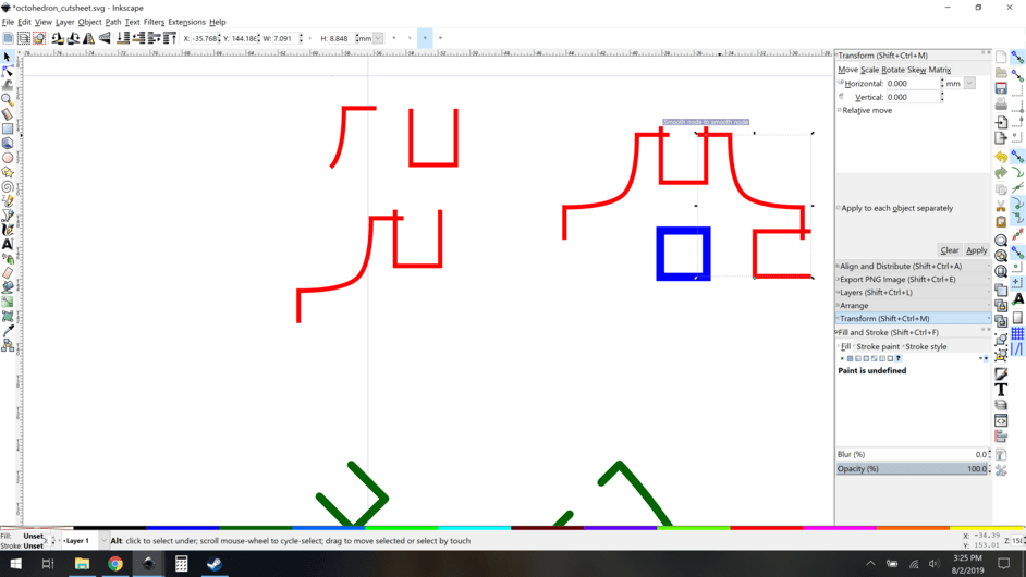
So that angled corner piece is only half of the desired end piece, so I cut and paste another clone, then with some rotation and flipping, I match them up and then group them:

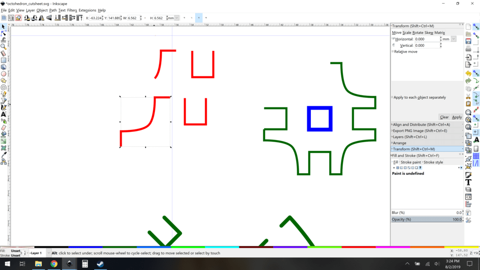
Now I align them to each other. Now you can see why preserving the original nodes was important, they overlap with some “slack”.


Now it’s important to take a second and see what we did there. We have two paths at top in red. The two overlapping clones underneath are made entirely of clones, which means that if I modify the original paths, the changes push forward into the new cloned parts. This is the core of why I’m doing this, more later.


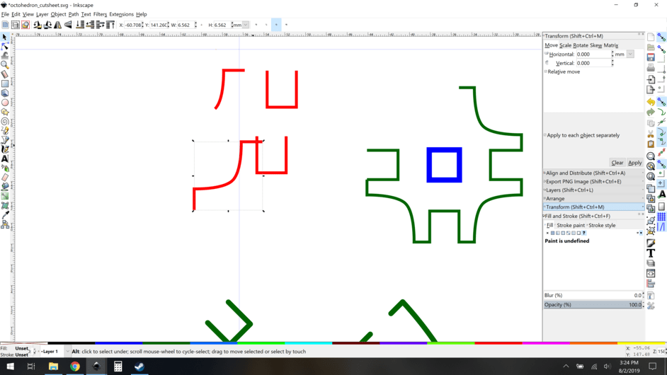
OK so we have our new clones corner assemblies, lets take 4 of them and rotate/align them to each other. First, group the entire thing.

Now clone that group of clones, and use that to make copies and rotate/align them to each other. I’m going to go fast here, 5 images in a row showing the basic steps.

Clone the group


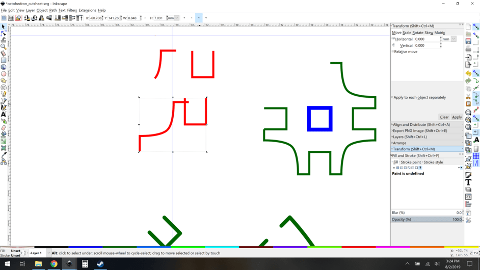
Snap to original shape

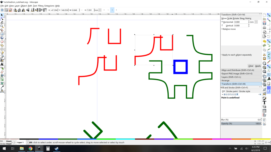
Ditch original shape.

Copy the cloned group, rotate 90 degree, and snap it to the first one.

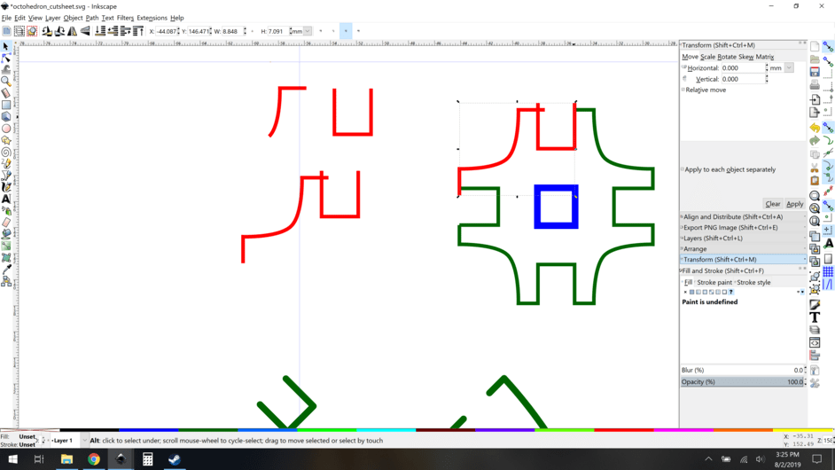
Repeat the process 2 more times and you’re done!


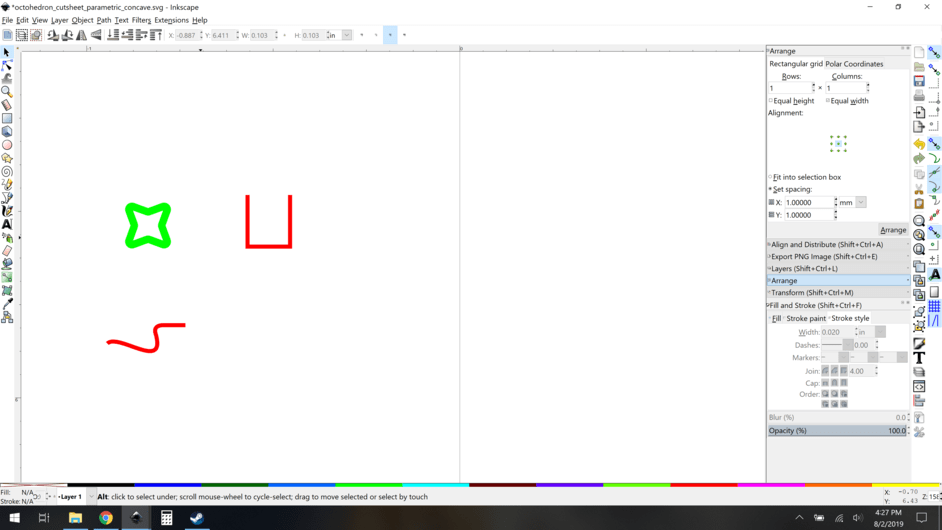
OK so now you have your recreated part. What now? Well, me, I didn't like those sharp corners, so I decide to ease them a bit. All I do is go modify my original path to have a small rounded corner:

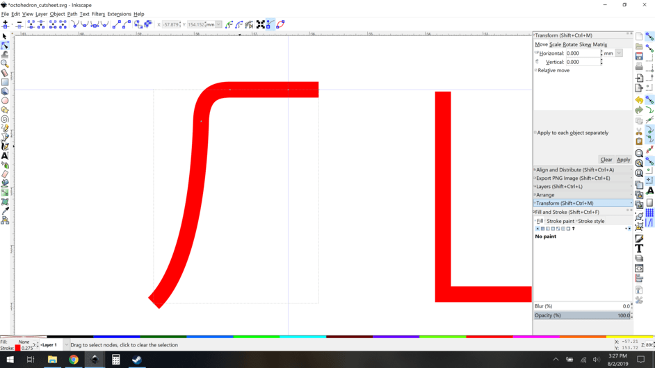
Now I go look at my part, it’s all set!

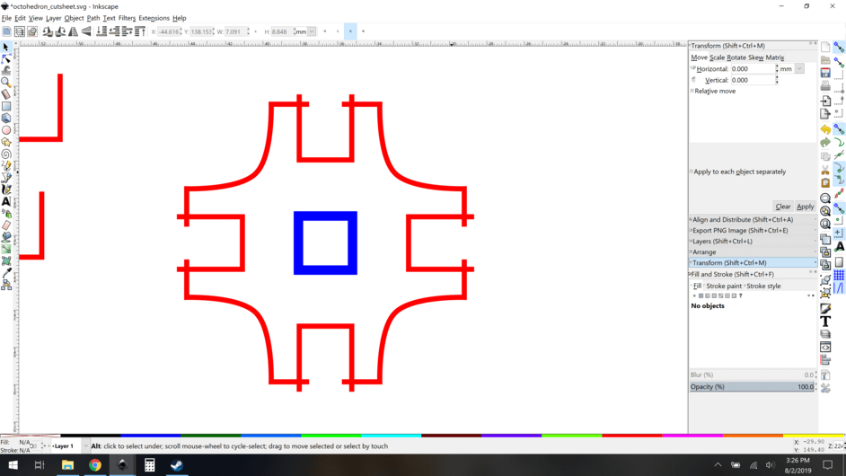
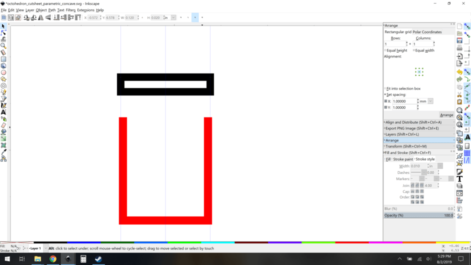
Now the real meat of the thing: slot width. This was originally designed for thinner material and I need to widen the notches, The quick and dirty way is to just scale the whole svg, but that changes the scale of the final assembly, and I don’t want that. So now, we can just widen the one notch path and all of the clones will follow suit! The trick is that you have to widen it symmetrically, push both sides out from the center. Lots of ways to do it, but here is a simple visual way:

Make a rectangle at your desired width. Align it using the extra node in your notch from way back and a guide. Snap guides to the edges of the rectangle.

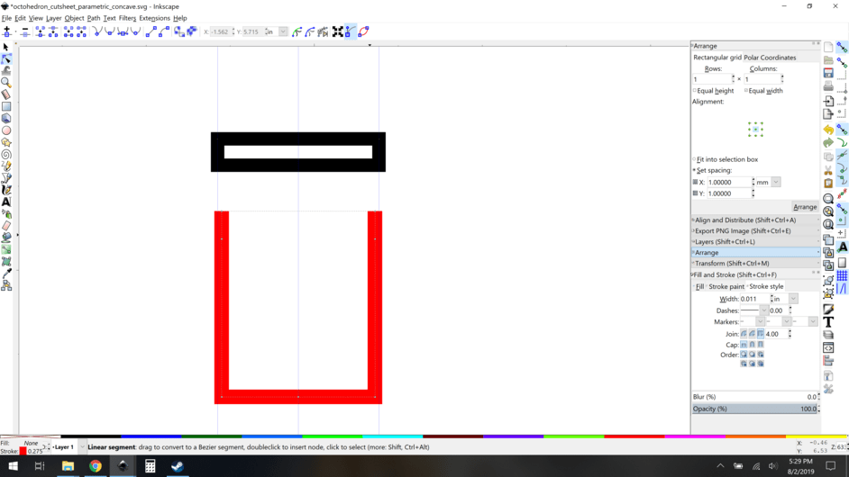
Move the nodes of your notch to hit those guides.


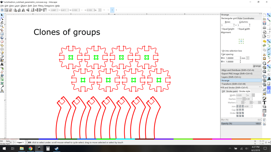
So there you go, that’s the basic idea. Whats next? Do the same sorts of things for my curved components. Pull the piece apart, make a base path of the arcs, and then put cloned slots in place. I’ll skip the intermediate steps here, and show you how it turned out:

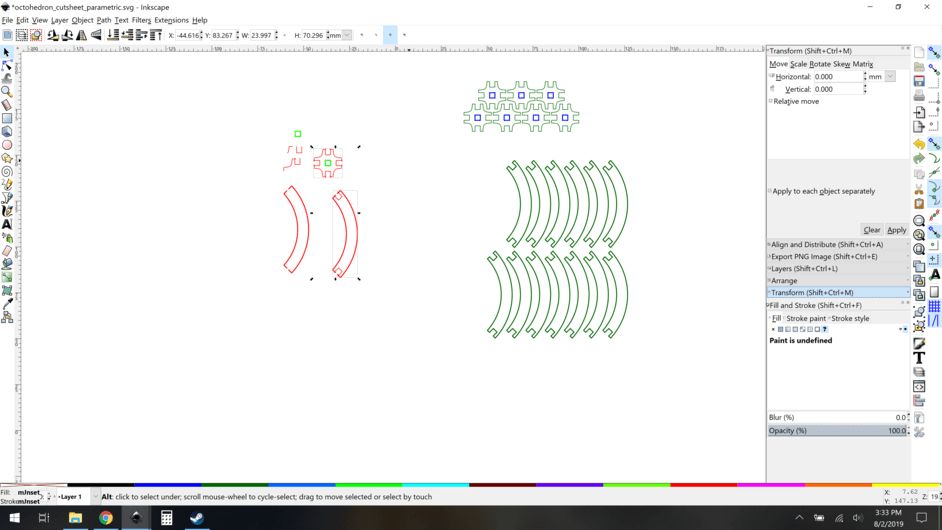
So what now? OK now we need to get ready to cut them, so lets use the arrange tool and whatnot to make a nice tight grid of our parts and also ditch my old green paths. Then add a few text labels to make sense of it all.

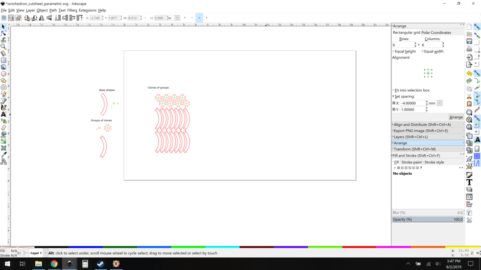
And that’s all you need to do.

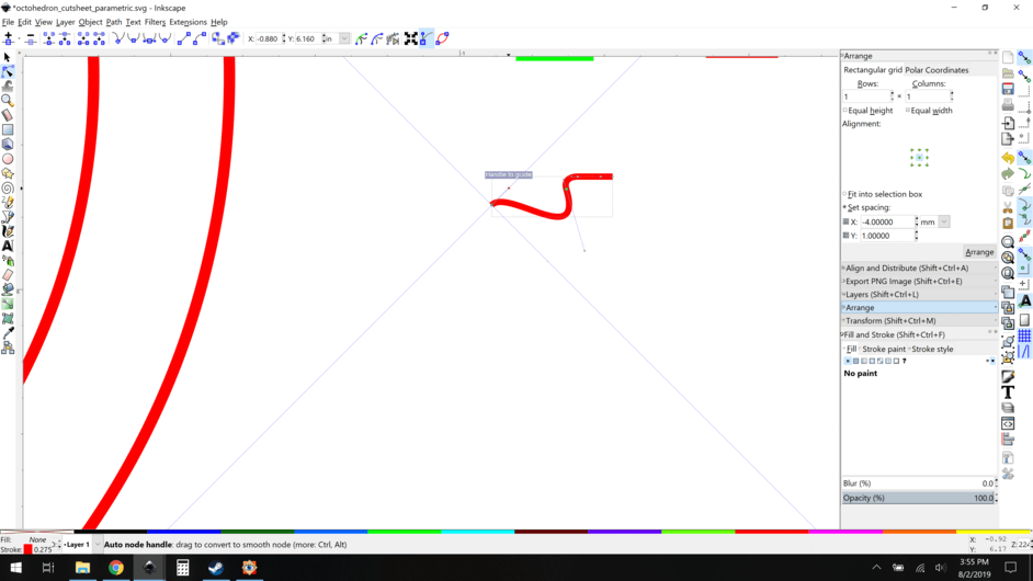
I decided that I would modify things a bit more though, since I could and it was easy… Let’s put a wave in that corner. The fun realization here is that if you place the end node anywhere along a 45 degree line means they’ll match up. It’s the axis of symmetry. Add a guide, and go nuts.:

The end result had an ugly transition, I didn’t like how the curve was broken, too sharp.

So to the bezier editor. To make this a nice smooth transition, make sure the handle
on the connecting node is perpendicular to the axis of symmetry, using another 45 degree guide:

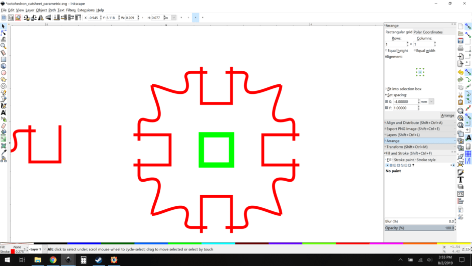
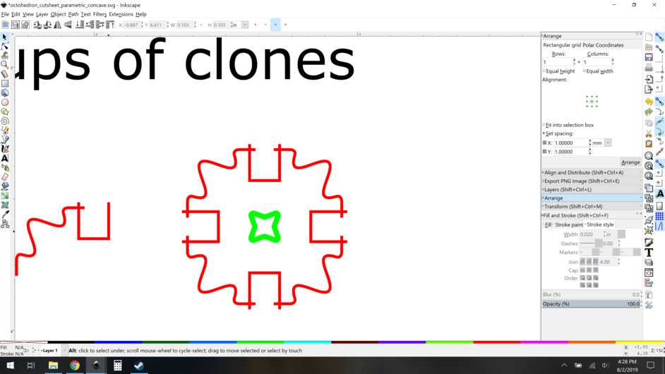
Now let’s put some style on that central hole:

And now the final result:

Likewise, you can use similar tricks to modify your arcs. Here’s a concave version.

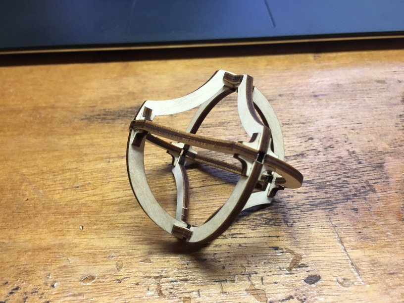
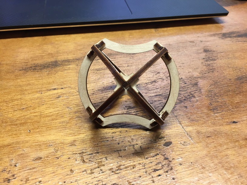
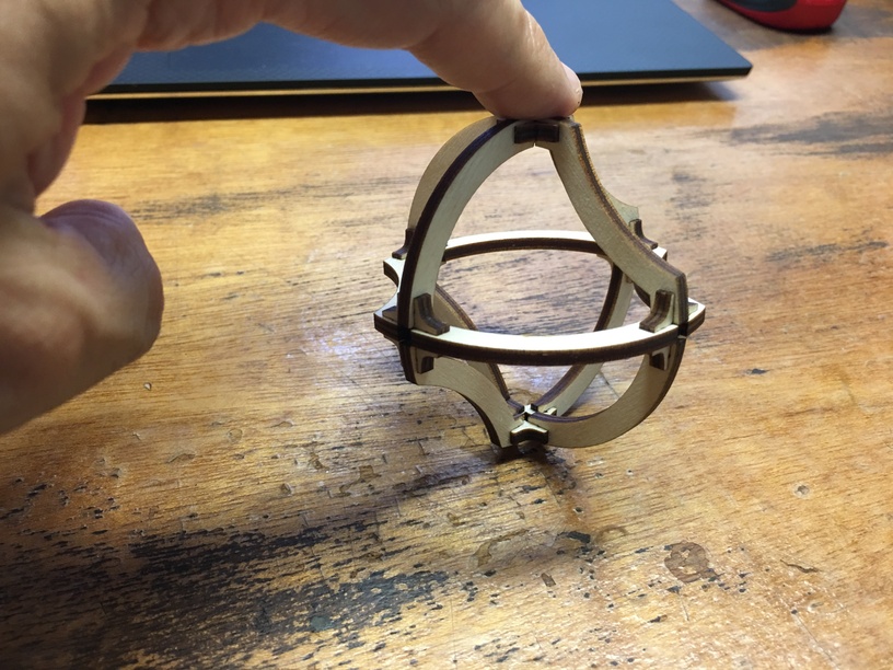
So, what does this give you? These guys.

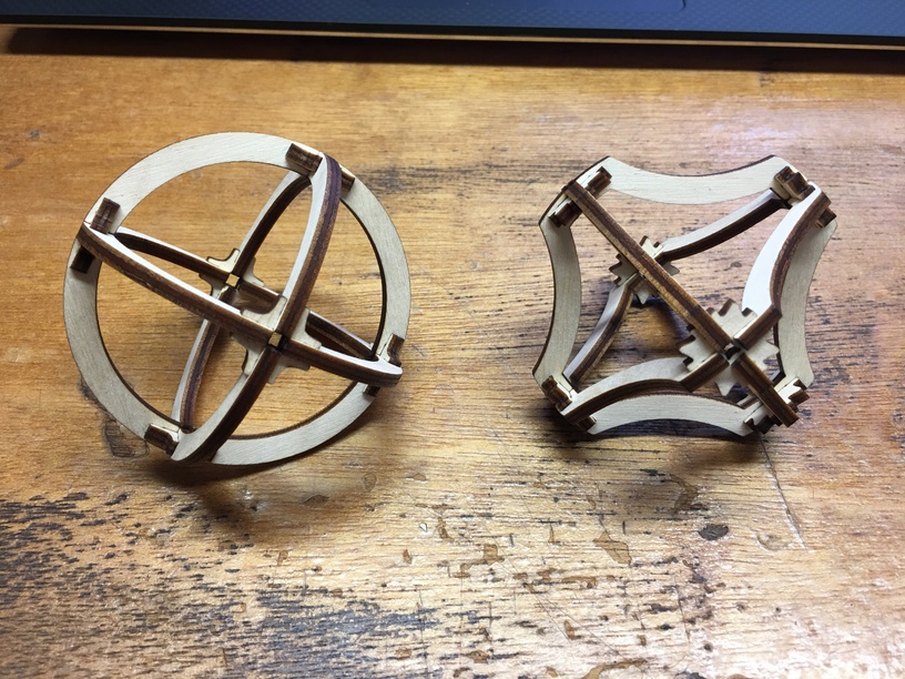
Extra fun: I never moved the slots/tabs relative to each other in the parts, so I can mix and match these! Behold the chimera creature:

Anyway, it was long, if you made it this far, gold star. Hopefully this is useful to someone.

Want to make them and fool with the source SVGs? Here you go:

40 Likes

I’m probably just barely inside your demographic for this but I bookmarked for later anyway, I’ve always believed the more you know.

5 Likes

Super write-up. You are indeed a patient man. Definitely added to the collective knowledge here.

3 Likes

Patient for doing the writeup? I’d agree there, writeups are a slow labor. In practice the process I laid out is really pretty quick, if you’re pretty proficient in Inkscape. I’d say if I did it without wrangling screenshots and writeups, it’s a 15 minute process tops, including fiddling with the design (which I honestly didn’t take much time doing, it was just spur of the moment additions).

It all comes down to how comfortable you are with snapping, guides, and clones. At this point, they’re second nature to me.

6 Likes

Yep. Good documentation is a labor to produce. It’s a lot of work to get it clear and comprehensive without being overly complex or too short & simple.

3 Likes

I don’t use Inkscape … but, think you were very clear and concise. Think there will be many who will appreciate this!

1 Like

I appreciate your liberation from the tyranny of closed shapes. I need some mental reprogramming to allow over-cuts to be “okay”, seems like a great pathway to more flexible design files.

3 Likes

I agree. I’ve gotten a lot better in F360 since I realized that I can do what people who sketch on paper do. Make lines too long, draw an ellipse only to trim away 90% of it. Draw a rectangle for the start of something that won’t be anything like a rectangle when finished…

5 Likes

Exactly this. The overcuts that go “into” the notches are necessary to accomodate things if you make your notches narrower in the future. If you don’t extend the paths to overcut, you can end up with partially cut pieces which would be bad.

3 Likes

This is a masterpiece of explanation and a great use of Inkscape. I’ve thought about using the clone tool more productively to use it as parts of a bigger assembly, but sometimes getting over that initial hump to figure it out just makes me do the easy thing, even though I know I’d have to redesign the whole thing if I wanted to use different material or make it a bigger size.

2 Likes

Soooo, that’s the other thing to watch out for.

Once you get to too many parts, the GFUI panics and won’t let you separate the clones from the originals – it groups things. So for those cases, I save out a new cutsheet, and destroy the off-screen bits so that all that remains is the grid of parts. Deleting the original paths instantly de-clones them, so it might take a minute or two when you do it while inkscape reconsiders its life choices.

This was the case when I posted that recent 400+ part de-masking.

This is a cloned sheet, but I had to make a copy of the file and unclone them. Just too many paths for the poor gfui.

Of course I kept the cloned sheet, because that’s the point, but when cutting you may have to undo your cool clone array to get it done.

4 Likes

That’s very clever, it’s the overcut bit that really opens up the possibilities.
Re spliting out the clones there is an option to do that somewhere.
I have a bunch of things I sell where there are four identical shapes on the sheet and I use clones for those, sometimes they are great, sometimes it’s just easier to copy out four items again. But cloning is really powerful.

But, the idea of breaking the object and over-cutting - that is the real trick here.
Excellent idea and write-up

1 Like

It’s under Edit->clones->unlink clone.

Or if you’re doing a one-off cut sheet, it’s “delete key” on the original objects :slight_smile:

1 Like

You mind is beyond compare figuring this stuff out!:astonished:

1 Like

Not at all, not at all. This is just me trying to hack my way to a more adjustable way of doing things, given my complete inability to get familiar with F360. I just find it so cumbersome, so I did this out of desperation.

The funny thing is that we all have different ways of approaching these sorts of actions that to us, whatever we’re doing is “normal”. This always seemed like the obvious way to do things, but I know that is a completely subjective concept. Almost everyone has a trick or two that seems simple to them that other people will think is pure genius.

Like, I bet @rbtdanforth reads this and is like “you’re doing it all wrong!” :). He uses Inkscape to great effect, but often comes at a problem from a very different direction from mine, right down to using different commands to get the same results on some of the more granular actions. This is why I love reading other people’s process descriptions, you get a ton of perspective and new ideas.

BTW, for a direct rbtdanforth influence here, he was the first person to tell me “look at the arrange dialog”. Now I use it on almost everything. Seriously, if you use Inkscape and don’t know about arrange, go check it out.

Anyway, this is me trying to give back, hopefully some of you get some use out of it.

7 Likes

Okay, you are no dullard in any way, I think this shows just how different we can be internally and still seem pretty much the same species when talking to each other.

1 Like

I also struggle when trying to design with that tool… I think I’m unconsciously fighting too hard to make it work like it “should”. But it certainly doesn’t provide a garden path to success!

2 Likes

I’ve had that problem with other softwares until I learned to bend with code.

After my first real project with F360, during which I cussed, started over, threw things at the monitor, etc. and took days instead of the hour and a half it should have taken, well after that, F360 has come relatively easy for me.

Maybe too easy as I’ll often go there for something simple that I should just do in a vector program.

3 Likes

I sure appreciate being able to follow along your train of thought. Always learn something! Yes, I’m familiar with the arrange dialog. You mean Align and Distribute right? Or is there something else I missed. A year ago I downloaded Inkscape for the first time and didn’t know how to design a simple keychain. I’ve learned a lot over the last year - with great enjoyment.

1 Like

I am a leaf in the wind…

2 Likes