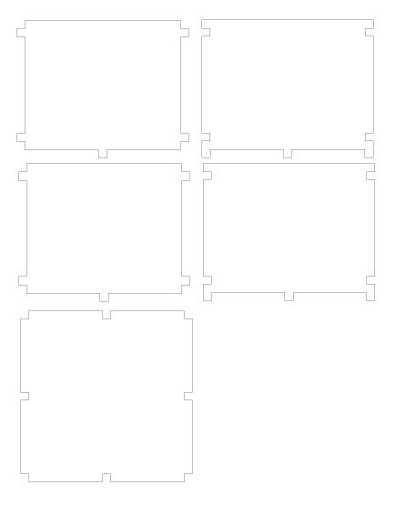
Okay @smcgathyfay, here is the laser file for a small box with tabs all over it. It has been created for:
Material thickness = 0.124 inches (3.15 mm) plywood
kerf = 0.006 inches (.1524 mm)
The file is already kerf adjusted - you wouldn’t need to do anything to it except cut it. The parts will likely be too tight, but I want to get an idea of how much “adjustment to the kerf adjustment” that we need to make. Chuckle!
I put it in .DXF format - wasn’t sure what format you prefer to work with - just let me know if you need something different.
In my experience kerf is something that isn’t that constant. From machine to machine or material to material. This will get you a decent ballpark but I wouldn’t design around it. Just a heads up.
[quote=“nick07lee, post:2, topic:3250, full:true”]
In my experience kerf is something that isn’t that constant. From machine to machine or material to material. This will get you a decent ballpark but I wouldn’t design around it. [/quote]
That’s one of two reasons why we’re running this test.
Setting kerf and thickness up as variables makes changing the kerf very easy. (Literally drop in one number and re-export the DXF files.)
I want to see how tight a kerf adjusted file is… @smcgathyfay has volunteered to test one on her laser, and those are the settings for the material that she has, and the laser she uses on it.
(Since she isn’t using F360 yet, I’m dropping the numbers in and doing the exporting. She’s just helping me out 'cause I haven’t got a way to physically test it yet.)
The other thing we’re testing is the tab parameterization, as shown in the two examples above. That changes by dropping in one measurement for the thickness of the material.
It’s kind of a long way around doing testing, but it’s better than sitting around on my hands! Chuckle!
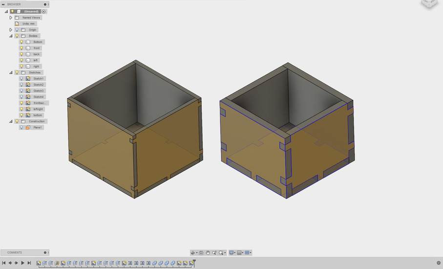
I haven’t looked at the DXFs, but the render shows a problem with the box. The bottom piece is too short (it appears to be off by one material thickness in each direction.
(edit - I checked out the DXF and it looks fine there. Strange that Fusion rendering it the way it is. I’ll leave the rest of this post how it was.)
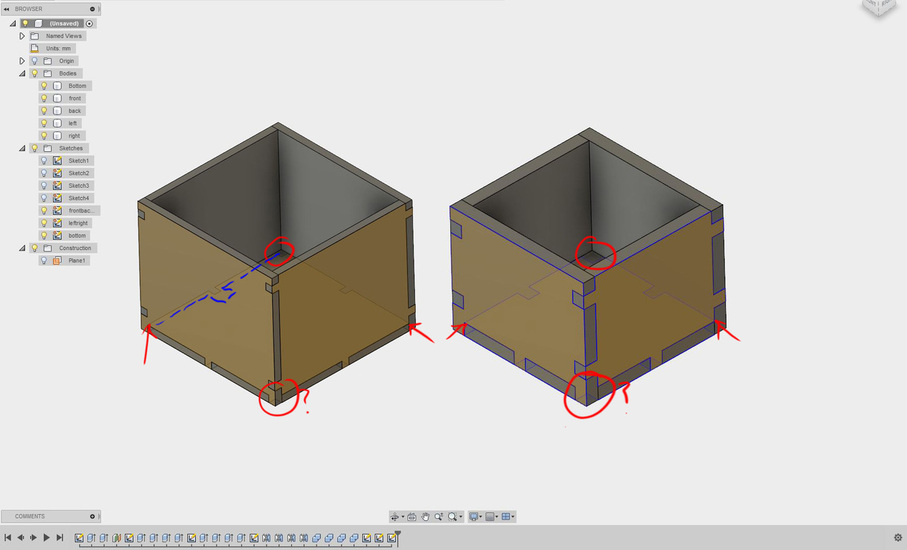
After looking at it a little closer, it also looks like the there’s a corner on the bottom piece that’s intersecting with the front piece. And, with that being the case, it appears that the slot in the middle of the box is off-center.
Or, maybe Fusion360 is just rendering it weirdly. The back and left slots on the bottom piece should not be where they’re being shown (I highlighted one with blue).
Yeah, I didn’t turn off all of the sketches before capturing a quick screen shot for the 3D. (My bad.) Some of them are showing through at a weird angle.
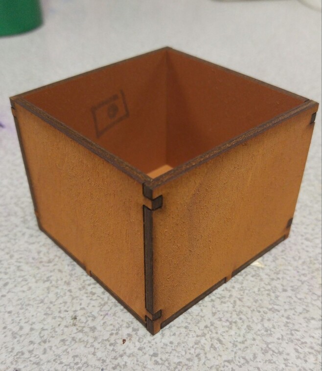
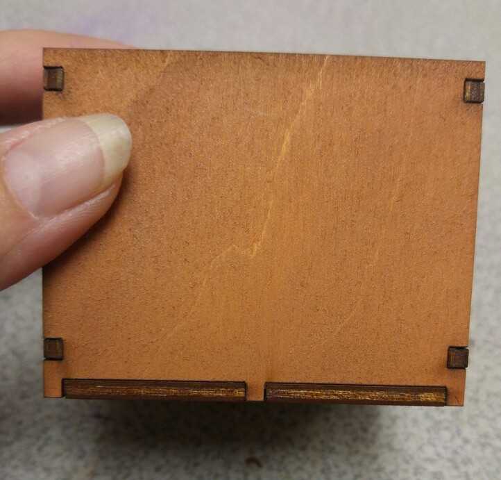
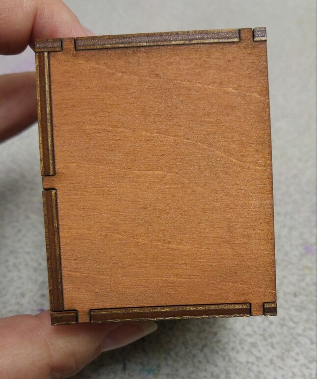
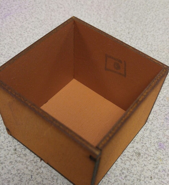
The tab architecture should work though, if I’m lucky. It fits together like a puzzle…(iow…it’s supposed to look like that. Chuckle!)
Managing tons of extra features and sketches can be annoying, especially when they’ve only been added to the design to deal with the manufacturing side of making something.
A complicated design could turn into a full-on quagmire pretty easily.
True, it can be messy, but I’m the only one who sees it. (Unless I post a screen shot as an example somewhere, and forget to turn everything I don’t need off.)
One thing that is a bit of bother…you do have to remove the supporting structure path once you have exported the DXF, and let me tell you, they are CLOSE together with a kerf this small. Very easy to grab the wrong one for removal.
Just one more step though. Frankly doing corner rounding on cut files in AI to keep the blade from hanging up was a lot more tedious. Depending on the file, there could be hundreds of them to deal with. (Another reason to go for the Xtream Path plugin, which deals with that all in one swoop.)
Already got a couple of those cookin’!
I want to see the results of these tests to decide whether or not the pursuit of kerf makes sense for those kinds of files. If it’s negligible, I’m gonna drop the issue like a hot potato, and let someone else who cares more about it figure out how to go about doing it best.
I’ve figured out a way to kerf-adjust if it becomes necessary, so that’s all I need for now. I can see using a kerf adjustment for a few types of files - inlay work being the prime candidate, maybe some transparent acrylic work where I want parts to snap together instead of using glue, but even those are going to take further thought and testing, to keep the acrylic from splitting due to a too-tight fit. (dogbones, probably, but I plan to test corner rounding as well to distribute the stress in the corners)
Other than that…I’ve got a loaded glue gun and I’m not afraid to use it! Chuckle!
This is the interesting part. Once everybody knows what they’re doing it gets boring fast.
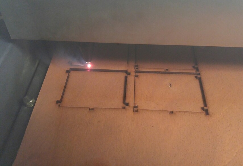
Resisting the urge to check the file…I sent it directly to print. The only thing I did was change the line width to Corel definded hairline (its what my laser recognizes from Corel for vector cuts)
There’s just a bit of wiggle room at the joints but fits well enough to hold but would require glue…
Not necessarily a design flaw but could be an inconsistency in the material.