Passthrough Alignment Tutorial with Manual Indexing

Really great! Bonus points for noting paralax error!

4 Likes

Thank you for your diligence and willingness to share the process! :+1:

3 Likes

Yes indeed! Absolutely, positively! Excellent explanation! :grinning::+1:

(I’ve noodled with something similar, but without the slot to test it yet…your technique is pretty much exactly what I had in mind. I’m thrilled to see it work. Thank you!)

4 Likes

Wow, what a write-up. Thank you! I too am new to AI as a GF owner. This is helpful.

3 Likes

Looks amazing. I will have to read this again when I get to trying this. (Of course, :glowforge: might get the auto-align working by the time I get to pass-through. That is a nice feature, but I went Pro mostly for filter, increased power, and active cooling.)

2 Likes

Nice tutorial!

I’ve been a HUGE proponent of a cheap Illustrator plugin from RJ Graffix for cutting up vector Illustrations for passthrough sized pieces. Adobe Illustrator plugins — rj-graffix

I place a guide and zip the “table saw” tool right along the guide and it separates the design exactly how I want it.
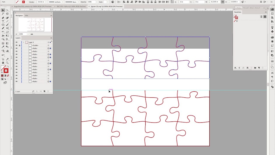
13 Likes

I think I’m going to try a couple of those - i see they’ve got one for concatenating that might be tremendously helpful on some of the CAD imports. :grinning::+1:

Not sure on the other tools - but the cutting tools, they give you 1,000 free uses as a trial.

2 Likes

Instead of scored fiducials (which as your point about parallax illustrates can be hard to get exactly correct on the subsequent pieces, you might want to consider a fixed physical alignment method. I use (on other lasers & CNC) finishing nails. Instead of a scored fiducial I “drill” a hole the size of the finishing nail and place a nail through it and into the bed (a wasteboard in the CNC and a sacrificial underlayment on the laser).

The other thing to consider is that when using wood, it’s easier to dislodge a spacer like your left side fixture because of the mass behind the movements. I use wood for a spacer - again either pinned to the side or inflexibly fixed to the machine. I usually do a piece of wood that goes all the way to the left side of the machine I’m using so it’s butting up against something that’s not moving. For fore/aft movement prevention I butt it against the front or the back of the machine to the side of the doors. That makes the jig referenceable to the machine vs just the tray - the machine walls are in a constant position, the tray can move on the GF.

I don’t have my Pro yet but I’ll build a similar jig for that. I’ll pin it to the crumb tray after drilling a couple of small holes in the tray edge to allow for finishing nail pins. That isn’t modifying the machine so should not affect the warranty (except maybe for the tray).

I did some stencils (19.5" wide by 28.5" long) for an artist locally for some street art he was painting. The stencils were individual colors that after each was painted formed a 4 color picture. So I had to get 4 stencils for each painting that were all oversized to register to each other correctly after being cut. Relying on the bed to provide the registration wouldn’t work.

8 Likes

I worked up some pegs that fit down into the grid holes last night. Idea being - one peg hole in the design somewhere, cut the hole for it first then proceed, and rails along one side - should give perfect 3 point registration.

(I’ll test it once i get my machine. And that’s assuming that the pegs will fit in one of the new tray grids.)

Anyway, no rush, it should work out pretty well given the tutorial above. (And I don’t have to write it up! YeeHaw!) :smile:

Whoop! Time for the F360 webinar…

6 Likes

Yep that will work too. I have cutting some honeycomb pegs on my list. @takitus or @karaelena posted about their design back early this year. Was waiting for my machine so I can match my honeycomb specifically.

I do try to make my registration pins as small as possible though so they don’t get in the way of my design.

A lot of good thoughts here. I think that making the guide run the full length front to back of the machine would make it less likely to slip. It would need to have tabs at each end, probably vertical would be easiest, to keep it from sliding through the slots.

The crumb tray has the lips on the sides that are exactly 20” apart. If you wanted a guide to overlap them, it would need to be contoured on the bottom. Having seen the discussions about measuring the thickness of the crumb tray, I was concerned about whether pass-through material would lie flat on the tray, but the front and back of the tray are level with the honeycomb.

It seems like pinning to the tray has the same problem of possible movement. I do not think this is a significant issue since you can be consistent in pushing the tray to the stops…say left and back.

The thing I like about having the fiduciary marks generated by the design is that it completely removes variations of calibration. The design is completely self contained.

Combining that concept with pinning, however suggests the following to me: make small registration pin boards that fit into laser-drilled fiducial holes in both the guide and material. The pin boards would be small boards, maybe 1” square with pegs (e.g. finishing nails cut off) sticking through the bottom.

The guide fiducial holes would be cut during the first panel and each panel would cut the corresponding holes at the bottom. Having two pins in each side would prevent pivot errors from introducing slop.

You could also have a pair of such fiducials on the door side of the guide and process the cut in two passes. First pass, cut the fiducial holes. Then cut the design, having the registration pins holding both the top and bottom of each panel.

The benefit to having the pin blocks sit above the material is that you only have 1/4” of slot height, so putting sacrificial material under the product uses up some of that thickness. Your stencil example would be OK with that. 1/4” ply not so much.

So, lots of refinements possible!

2 Likes

What a nice write up!! Your efforts are very appreciated!

2 Likes

That looks great! And $10 is cheap. Looks like I’ll have to wait a bit, however, until they get CC 2018 supported.

1 Like

I’m on CC18 (for Mac) and it works great. Not sure if you’re on PC. Looks like the PC-version hasn’t been updated yet :frowning:

1 Like

Yep. Windows here. I don’t do Macs.

1 Like

Correct & correct. Pinning to the crumb tray is for pinning the alignment jig that is locked into the same place all the time by the side/front or back. The pins to the tray force the tray into the same position all the time - so any movement back and forth due to slip in the little divots in the base won’t affect registration. The jig is always in the same position and because the tray gets locked to the jig, it will also always be in the same position.

For the GF my jig will be to the edge of the black rim on the left side up to the edge of the honeycomb so you still get the full bed available. As they improve the usable bed size until it gets to the full 20" size it will still work.

Then you can use pins in the bed for your fiducials because they’ll always be in the same place - not just within the execution of that project but for all of your projects. :slight_smile:

The other machines I use have bed height adjustments so the use of a sacrificial board to pin the fiducials to isn’t an issue. For the GF you’d need to make a bed that you could replace the crumb tray with. If you’re good with pinning the jig to the crumb tray as I’ve outlined you don’t need to create a sacrificial board.

I outlined the whole process in a posting last month on using pass-thrus in general and suggestions for how to do it with the Pro.

3 Likes

YES! Thanks for the fantastic documentation. Big Ups!!

Terrific work writing this up! We’re hard at work on the software to make this unnecessary, but in the mean time, it’s a great resource.

6 Likes

And I had completely forgotten that @johnse had already written this up…there’s just too much going on this week… but this is pretty much the method I used, so I’m certainly not going to write it up again. :roll_eyes:

I got some really excellent results though that I’ll share, to show how well it works…it was beyond exciting to see results that good on cheap warped hardware store plywood with my first couple of attempts …

Passthrough closeup 1

And because I was told that diagonal lines are the true test of alignment…a triangle.

Triangle Test 1

triangle test 2

I really wasn’t expecting it to work that well.
(Totally thrilled with it.) grin

ovals

6 Likes