I’ve been thinking about this and again will do some sample cutting (last night wasn’t the right night for laser work). But the tolerance for a spline can be set - typically it’s a factor of 10 as a default when you convert a spline (I have no idea what this means) but I’ll do some test cutting to figure that out. BUT - why would it matter? If both mates of a cut are using the same technique, and something is segmented on both sides using exactly the same line for cuts (offset to compensate for kerf) I’d wonder if you’d end up with gaps. I could be completely wrong and perhaps the line segments with the offset would produce a gap, but at that small of scale I can’t believe you’d even see them let alone have them throw off the cuts.
Ok - so first tests from AutoCAD - and granted I’m both stealing a design from evansd2 (who is AWESOME BTW) and trying this on proofgrade materials. I plan to order some 1/8 hardwoods from the various Ebay shops in the next few weeks as soon as I figure out exactly what I want, then I’ll nail this down further.
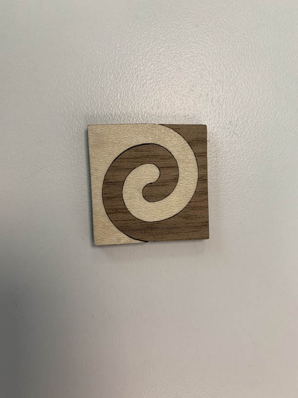
First pic - this is cutting 2 segments, one out of Maple, one out of Walnut, and the kerf on the Walnut is offset .005 - when I tried to do this with both segments, the pieces wouldn’t fit together as that was too much compensation for the kerf. It’s not perfect, and in watching the laser fire and cut, I’m puzzled as to why it cuts the way it does. Everything is on the same layer in CAD, and these are circles, cut into arcs, changed into Plines and joined together. So it is a contiguous line in AutoCAD but it treats it on some level as just arcs. It’ll cut the bulk of the arc together, but the small “cap” on the ends that’s a .1 arc, it doesn’t continue around that arc, it does everything then cuts it at the end of the cut. Weird.
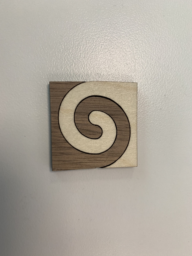
You can see what evansd2 is talking about with the laser cutting at an angle. That’s the same piece with a very tight kerf, but there’s a significant gap. Honestly the gap looks pretty cool as it adds a black line around the cut, kind of like a micro inlay, but if that’s not the look you’re going for, more kerf analysis is needed. Luckily evansd2 has given us many many posts on all of this, so all I need to do is figure out the “resolution” issues with CAD.
I say this as the arcs aren’t very accurate, which I think is a function of the PDF I’m creating using the plot command. I’ll test that theory more tonight (unless I’m painting the upper hallway).
Are you cutting one piece right side up and the other upside-down like (I think) @evansd2 does? That matches the slants and lets you get a little tighter with the kerf.
Another trick is to set the focus to half less than the height of the wood – @jbmanning5 does that with his puzzles, and it makes the kerf look smaller on the surface. (Updated per @jbmanning5’s response below)
As for the laser path – your arcs must not be connected. They need to be joined into a contiguous line segment for GF to treat them as one continuous path.
Basically flip one side in your art horizontally before you cut and go from there. You’ll get more even kerf compensation and can most likely up the amount you’re compensating.
The tricky part is knowing how much to correct because if you go too tight you can deform your pieces and end up with strain escaping as a deformation at the edges. We’re actually seeing the beginnings of that in meinken’s piece, you can see how the edges don’t exactly match up. That could be down to a missed symmetry in the source art but it often comes from going too tight on your kerf adjustment.
For most hardwoods and other 1/8” material, 0.006” is a good starting adjustment… if you’re flipping one piece. If you don’t flip, 0.006” will probably be too tight. @mrinken, how much was your kerf adjustment? Oh wait… he said 0.005”. Yup I’d say that’s too tight by 0.001 or .002 for a non-flipped inlay, and the pics seem to bear that out.
Nope - I wasn’t doing that. But this was a first test - I’ll set the kerf adjustment for .003 tonight and flip the design before the cut and post some results. Again, this was proofgrade, not sure that matters (and I was using proofgrade settings).
Now I just need some good 1/8" hardwood…
And my buddy who owns a cabin up in Grand Lake said it’d be cool if I could do this for his drawer fronts on his drawers with a pine tree cutout. Going to give that a whirl too…
OK well if you’re going to flip the cut .005-.006 should be fine. They are what I call a “loose” and “firm” glue fit at that range, usually. If you’re going to leave it unflipped, I’d probably back down to .003.
Of course everything changes a bit with each material but generally .006 is a good firm glue fit when flip-fitting.
FWIW, this is an issue i see all the time coming out of Revit when the architects i work with take a floorplan and export it as a PDF. something that may look like a contiguous line/curve in revit is now a series of shorter lines with points in them. i think there’s something that happens when the CAD file is converted to PDF. if you try opening that PDF file up in an illustration program (like Illustrator), you may find that it’s not one contiguous line any more.
In observance… after revisiting this Planar Butt thread… (again!) I suspect that if @evansd2, @marmak3261, @Jules, @PrintToLaser, and @geek2nurse have not attempted a project, it is likely out of reach of a mere mortal. Truly, thanks to all of you for input and inspiration.
Yes When Autocad went to Splines it started creating a mess. the difference between an ellipse by 4 arcs and an ellipse by splines is almost indistinguishable, so in trying to be more mathematically exact they created a whole lot of problems, not least that they cannot be attached to polylines,
When going to Revit they stayed with splines and thus a bunch of unsoluble lumps when you come out to normal vectors. I think there is a setting that forces all elliptical shapes to the old arcs system, but that only works when creating new stuff and is not retroactive,
Yea, I’m doing some experimenting and trying different arc types, plines, etc. The swirls I’ve created are circles that are trimmed, mirrored, moved and then converted into a continuous pline. I think my issue might be in plotting to PDF - that’s my next step in trying to figure out what’s the best way to plot it out and in what format.
Interestingly enough - when I do font cutting, I create in Illustrator, save it out to DWG, open in AutoCAD, explode the text block and generally scale / plot the resulting lines unless I need to do further work. Most of what’s there is a spline and those cut with no issues for some reason.
Weird. I have not been doing much Autocad in the past couple of years and that is with older versions so if I got a job now I might seem a noob, even with doing mainly that from 1988 to 2007.
I started with CAD in 92 and used it professionally for 4 years then into a hobbiest role for the past 27. I’m wicked fast in it so I can’t see myself designing in anything else. I have staff now that supports our company in all things Design Technology (Revit being the primary design tool) so I could possibly ask them. But their day jobs are filled with support requests so I don’t want to add to their burden!
Early on I learned Lisp and sort of divided from most folks as I could never move as fast but often accomplished more in less time by letting the computer do more of the job. I worked with one guy that his typing sounded more like a buzz than a series of clicks and had no interest even in making all the commands just a letter or two that was pretty close to my first project (this was before PGP ).
One I used in many ways both as hobby and job took information (initially the endpoints of a line) and used it to insert a block at those points with scale and direction by the other point of a line. As a next step, another turned one block into any other block. with any block made up of other nested blocks, exploded and then changed iterative design could be very fast and amazing results.
This was a piece I did in Autocad 11 that did not have solids but I made 3d meshes constructed by collecting points along polylines and then constructing the mesh point by point as they had to be and then deleting the array of polylines.
Yea - single key commands mixed with a 16 button puck on a digitizing tablet for wicked fast accuracy, mixed with transparent zoom commands built in = wicked fast. I sort of miss those days. Then again I spent months converting hand drawn house plans to CAD plans using the funds to live and pay for college. Tons of work but good cash.