Playing with beamwidth (aka kerf)

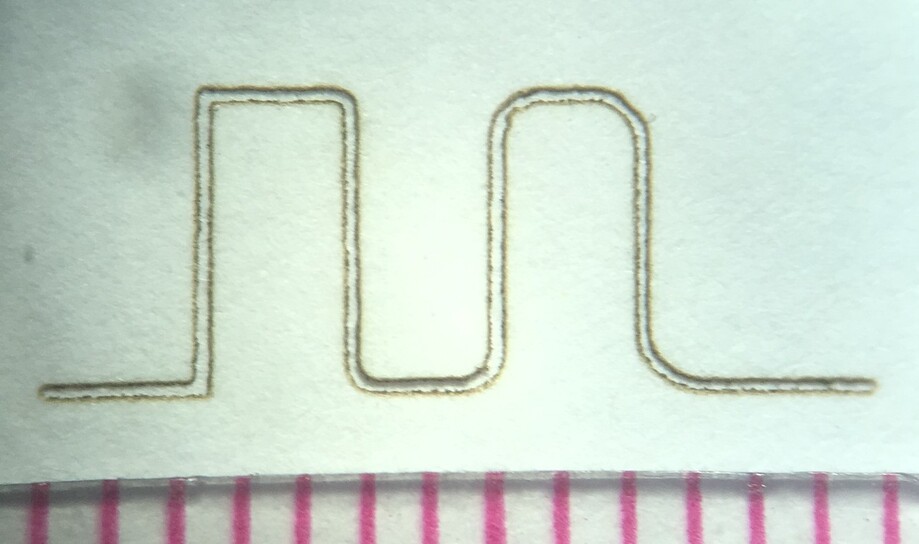
I’ve been playing with the focus height adjustment, and I thought I’d share what I’ve learned about it.

I got interested in the focus adjustment as a way to lower the applied energy of the beam. I’ve been cutting some materials with the power setting at just 1, wishing I could go lower. Defocusing the beam could be useful in that regard.

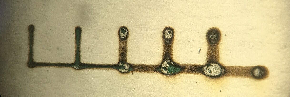
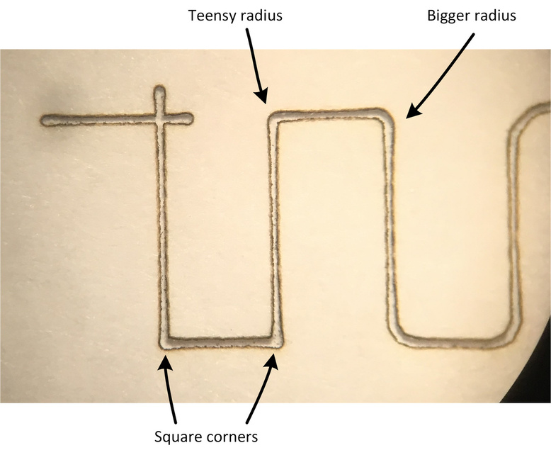
I set up my GF to engrave anodized aluminum, as that method results in a very stable kerf - once the adonization has been ablated the aluminum reflects most of the beam energy, leaving the kerf unaffected. To illustrate, below is a picture of a series of scoring operations with the beam power at full (non-pro version) and the speed stepped from 100 to 500:

image

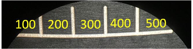
A 5:1 variation in movement speed, with no effect on the kerf width! - good to know when playing with engraving anodized aluminum.

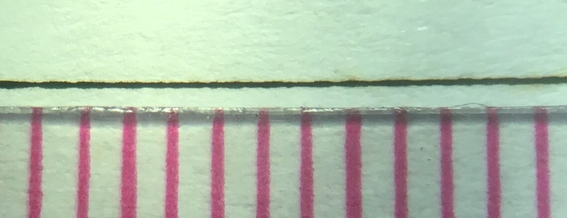
Next, I placed the anodized aluminum sample directly on the build tray and performed a series of cuts with the focus set to the sample height, sample height + 0.1", sample height + 0.2" and so on.

Then I elevated the anodized aluminum sample exactly 0.4" and repeated the same series of cuts, but stepping the focus height down instead of up.

This is what I got:
image

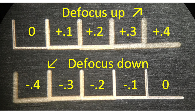
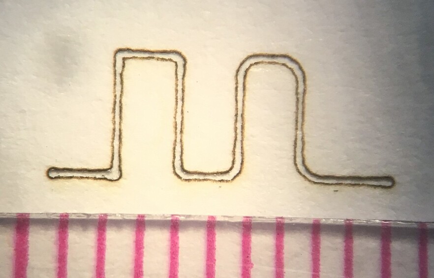
As you might expect, the kerf gets wider as the beam is defocused. The variation is pretty close to 2:1 with a defocus of 0.3". It’s also worth noting the edges get pretty fuzzy when the defocus is set to 0.4", which can be useful for creating smoother engraved areas - albeit at reduced detail - this has been well documented elsewhere in the forums.

So a key thing I learned, was that maximally defocusing the beam only doubles the beam width. So I don’t feel quite so driven to exactly measure and enter material thickness before cutting - I’m thinking 1-digit of precision is enough - or just let the GF figure out focus height like it’s supposed to do.

What can you do with this knowledge? Well, one thing I’ve played with is “beam nesting”. I complete a cut with two passes: the first pass is defocused to cut a wider kerf, the second pass is precisely focused such that the second pass lies inside the kerf of the previous pass. That allows me to lower the applied beam energy per pass, making for a kinder and gentler cut.

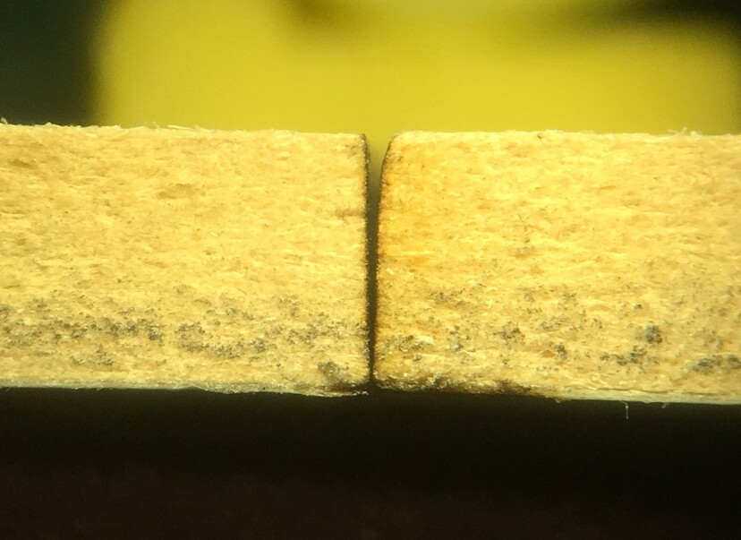
In the picture below are three samples of medium draftboard showing the as-cut edges. The top is cut using the Proofgrade settings - the cut surface is uniformly black from top to bottom as I’m accustomed to. The middle sample was cut with two passes, where the movement speed was doubled from the Proofgrade setting - there’s a clear demarcation between the portion of the sample that sees the laser beam once or twice . The bottom sample was also cut in two passes at double the Proofgrade speed, but the beam of the first cut was defocused +0.3 and the second cut was set to the material thickness - the result is a cleaner and more uniform cut edge:

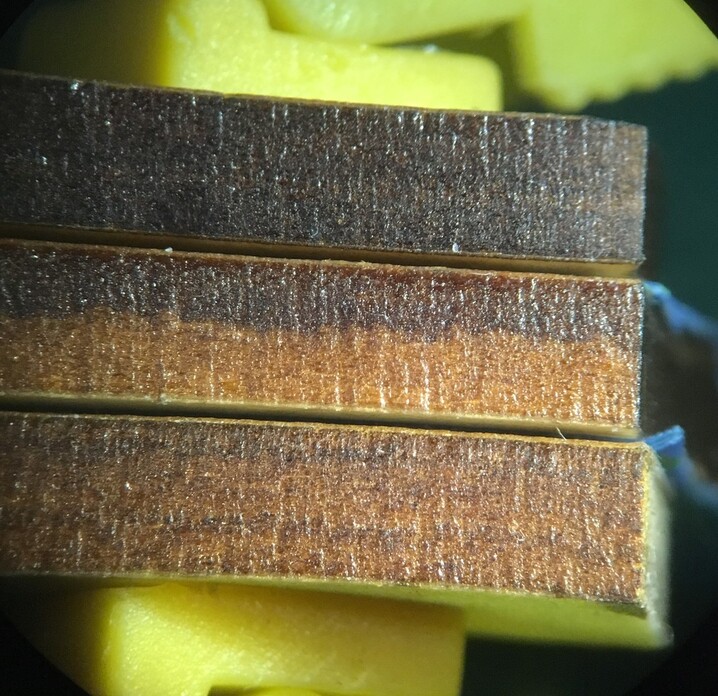
This seems like a promising technique for cleaner-looking cuts.

55 Likes

Interesting! Do you find that the cut edge is less perpendicular to the material surface (sloped cut) with the third cutting example you show?

2 Likes

Very cool experiments! I wonder how this technique would do with paper or cardstock. I’d like to reduce the char so I don’t smear soot all over the white cuttings.

1 Like

IIRC the material height affects the preview. The lid camera is a fish-eye lens. In order to dewarp the image correctly the material height must be known very accurately. The GF uses the red laser to measure the height for focusing purposes. So if you care about an accurate preview for placement of your cut and/or engrave, then you care about getting the material thickness right before cutting.

3 Likes

This is really clever. Thanks for documenting!

1 Like

Very good information, now if I can just remember when and how to apply it. I continue to want a way to save the settings with the file via the GFUI.

@Scott.Burns, the top 25% of the kerf is more rounded than the standard cut:

The lower part of the kerf is pretty similar. The overall kerf width is roughly doubled with the defocused beam, but the merits of a narrow kerf may be overrated in some situations, and either kerf is still way (way) thinner than most other cutting methods.

I suspect with some more tweaking the effect can be diminished… OR, enhanced to create deliberately sloped edges - for acrylic that can enable some interesting optical effects.

7 Likes

@AhnoldZ, understood about the GF’s built-in focusing system. That was one of their key technical differentiators in their early marketing. I’m thinking that is still a work in progress however, so I’m still learning to trust it. it doesn’t appear I can control where the thickness is measured, so I have to be thoughtful when placing items on the bed. I frequently drop in material that’s been heavily cut up, or place magnets that could land right under the measurement point.

@cynd11, for paper, defocusing is generally bad news:

The thinner the kerf, the less soot and char produced. The method I use to cleanly cut paper, is to set movement to maximum, power to minimum and dial up the number of passes until it cuts all the way through. The image below is standard printer paper, speed 500, power 1 and passes 6:

The ruler gradations are 1mm.

12 Likes

How do you avoid the big burn spots at the endpoints of each vector?

Great post. Honestly, one post like this is worth 1000 “look what I built” reports. I enjoy those too, but sharing techniques and material info that helps others is what makes this forum great, IMHO.

Thanks for posting this.

1 Like

@Scott.Burns, it’s interesting to note there is no blooming in the linewidth when cutting anodized aluminum, regardless of movement speed. The beamwidth appears to be well controlled, even when stopping one vector and starting another.

Nonetheless, I think fluctuations in movement speed is the issue that GF needs to keep working on. I’ve witnessed the laser appear to park-and-burn, usually where two straight lines meet - like sharp corners. When I see this, it triggers a childhood memory:
image

I’m a bit mystified why GF doesn’t see this problem and fix it. There’s no new science here, the 3D printing industry figured it out a long time ago, and the GF is basically a 3D printer with photons instead of plastic.

I try to minimize the effect by keeping the beam moving as quickly and smoothly as possible. I radius corners wherever aesthetically feasible so the software blends more smoothly between X and Y movement.

Below is a test pattern that increments the corner radius, from left to right:

This is standard printer paper, speed 500, power 1, and 6 passes. You can see a slight amount of blooming in the first (radius=0) corner. If you turn up the beam power, that will be where the paper catches fire.

If quality is a priority and you’ve all kinds of time to burn, you can cut paper using Engrave mode:

I converted the vector file to a 1355 DPI png file and rotated the image to minimize the line segments parallel to the X-axis (left-right) motion, as GF’s algorithm for thin lines gets dodgy. I set the engrave speed to 1000, power to 5 and 3 passes. It took about 15 minutes to complete - compare this to the previous vector-based run that only took about 5 seconds. Like I said, you can’t be in a hurry for this method, but my GF spends a lot of time sitting idle, and the time I spend cutting is typically a tiny fraction of the time I spend designing, setting up the job, and post-processing the output from the cutting process. Your mileage may vary.

8 Likes

Thanks for doing this—I’ll give it a try!

Variable speed corner work is something that’s been said is in the hopper. Granted we never actually get to see their to do list so there’s no telling where it is in the list.

1 Like

Have you experimented with extending your line segments to be an “x” instead of a “v”?
It might not work for interior corners, but it might work for exterior corners. The laser would just breeze right past the intersection then loop around and cut through it at full speed.

It’s something I’ve meant to try but haven’t found time.

@evansd2, good suggestion - that wins the square-corner contest:

Second place goes to the “teensy radius” corner, followed by the perfectly-square corners. For what it’s worth, the park-and-burn effect largely lands at the outside of the corners, so the effect is somewhat mitigated without over-extending the line segments.

5 Likes

Great data! To adjust the focus height, were you doing two separate runs and changing what the material thickness was set to, or were you able to somehow do it in a single run? If you did two separate runs, what did you have to do to ensure that things stayed perfectly aligned?

I initially did sequential single pass runs to determine how passes were needed. That process is cumbersome, and if the GFUI or GF hangs up I had to start over. As long as the material under test (MAT?) is pinned down, the registration between runs was excellent.

The images in this post were from a single run: I take the vector data and simply make a copy right on top of the original and set it to a different color. Once its in the GFUI I edit the settings for each path.

One note regarding editing the number of passes: when you click on the box you get a popup with only three choices (1, 2, or 3). Overriding those choices is a little tricky - I backspace over whatever number is currently in the box, type in the new number, then left-click in the box - hitting the enter key will revert the number back to 1, 2 or 3.

1 Like

That’s a good idea, but seems like it would be really tedious to do in vector graphics programs like Illustrator. Maybe Fusion360 has an option to do it automatically?

Depending on complexity and direction of the lines in question, no doubt. If all your line segments are orthogonal on the x and y axis (well really parallel along a limited number of directions is more precise), you can get clever with node splits and path break apart then group select all the nodes you need to move in the same direction… it’d be tedious for sure but not impossible providing your image isn’t super complex.

I bet the time it would take to adjust nodes would probably be less than the time to engrave instead of cut… but that may not be a fair comparison since engraving is a passive time sink where you can do other stuff and mode adjustment takes your focus. I dunno, this is all academic research that may or may not have practical application… until it does!

The true solution is for Glowforge to software this up and get rid of corner overburn. Come on, hopper!

2 Likes