Needed another three hands to put together, nice project! Thanks

13 Likes
A year later and your files are still in use! Thank you! I made 3 dodecahedra off your base design over the holiday break (2 lanterns, 1 solid backed).

14 Likes
Nice work!
2 Likes
Some tips from my polyhedron project in progress (pictures when done):
- Use Wikipedia (or remember Euler’s formula) to help figure out the number of connectors you need. Two per edge, not (e.g.) six per triangular face, which will leave you with twice as many as you need.
- Make a few extra connectors in case some don’t cut well, don’t fit well, or break.
- Copy-paste in the GF UI instead of in your graphics app is good for maximizing use of scrap from other projects.
- Weeding and peeling lots of connectors is a great job for kids.
- Measure twice, cut once. I misremembered that the sides were supposed to be 2.5”, not 2”, and didn’t check the connector fit until after I’d cut all my pieces.
4 Likes
Still not quite done, but some pictures and important notes anyway.
First: The file at the top of the thread has the wrong connectors for the icosahedron. (The connector labeled icosahedron is a duplicate of the dodecahedron connector. The dihedral angle for that is close enough that you can assemble triangles into an octahedron… with some difficulty… so it’s easily mistaken for that, too. My kids and I sure did the first time we tried to assemble it.)
I made my own icosahedron connector (144°) and updated the original file:

Whichever connector you’re using, you’ll be counting and printing and peeling a lot of them:
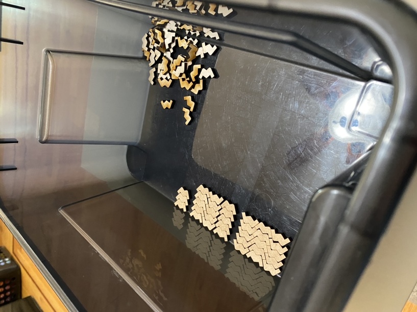
And then assembly is fun. (We’re taking a break between steps because we didn’t print as many connectors as we thought. It’s not easy keeping track while you’re making and arranging copies in the GF UI to use up your scrap!)
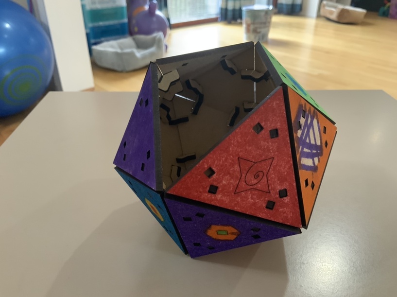
The bigger kid is learning vector design software, so some of the faces have scored designs of his; both of them got to color the sides. Proofgrade draftboard soaks up magic marker pretty well, but it still needs a lot of drying time if you don’t want it all over your hands.
10 Likes
This is awesome!
2 Likes
I’ve never made one of these before… How do you get the last piece on? lol
1 Like
Push and pray!
5 Likes
It looks like! lol.
1 Like
So helpful. Now I have a new way to sit in my room and ignore my family…Thanks!
2 Likes
Oh My Goodness - this rocks! Thank you so much!
2 Likes
@geek2nurse Thanks so much for this resource! Clearly they work as is since many people have posted successful projects. But for my own (GF newbie) understanding – when I pull this into my CAD program and measure, the offset from the face edges to the holes is 4.88mm, while the distance on the connectors from the internal angle to the tab is only 4.61. So it seems like maybe they wouldn’t quite reach the holes. Is this difference to account for kerf, or something like that?
1 Like
@geek2nurse will have the final word here, but in the meantime:
0.19mm is about 0.007 inches, which is a pretty good approximation of kerf in 1/8" materials on a basic Glowforge (especially when cutting slowly, like with proofgrade ply), so I think probably yes.
Faster cuts generally yield smaller kerfs. Basic machines are a bit slower than Pro models, and proofgrade ply is made of MDF core, which requires a fairly slow speed anyway (compared to BB or other easier-to-cut materials), all of which adds up to 0.007 (or a bit more even) being about right. The good news is that for projects like this even discrepancies of 0.005" (or maybe even more) is small enough that the end result won’t be noticeably affected. I think you’re good to go. ![]()
Because of that general “faster = less kerf” concept, things like cardboard and cardstock have tiny kerfs when focused properly. It’s rarely enough of a difference with most projects that you’d ever notice, but when doing tight inlay, for example, veneers cut with far less kerf than 1/8" materials, so it can be quite noticeable.
3 Likes
^^^ What he said. 
2 Likes
Thanks @evansd2 (and @geek2nurse !) for confirming my understanding (and quickly, too!) I’ve done 3Dmodeling/printing for many years but am brand new to laser cutting, so this whole kerf business is taking some getting used to! 
I have a Pro, not Basic - will this have a pronounced effect on the kerfs I can expect? Also, is the kerf “centered” on the cut lines? I realize this probably doesn’t matter for this application but inlay IS on my radar…
2 Likes
Kerf correction is a deep topic, I’d suggest looking at a few posts on the forum, it’s been discussed in some serious depth.
I like the “stroke to path” method in Inkscape. These will get you headed in the right direction.
4 Likes
Perfect, thanks!
1 Like
@evansd2’s approach to kerf helped eliminate a lot of my confusion; I was just 'way overthinking it.  I’ve started defaulting to about a 0.5pt stroke when I design, because that is pretty close to the laser’s kerf, and helps me visualize how the kerf will affect my design.
4 Likes
In Affinity. It should be the same in other apps, but tbh I’d use a true physical measurement if I were doing this. Points are supposed to be 1/72nd of an inch, but I wouldn’t put it past an app to go off the reservation on that.
(btw, 1/2 of 1/72nd of an inch is 0.0064". I tend to use kerf values of closer to 0.006"-0.008" for a pro, so not that different)
3 Likes
Oh, you and your Affinity-hating.  You can input line width in any dimensions you want; it just displays them as points after you do. And yes, it handles them accurately. 0.5 pt is about .007 in, which generally gives me a pretty decent fit on things.
2 Likes