Improving kerf adjustment on complex shapes

This is an inkscape-specific thing, but may apply elsewhere.

Kerf adjustment is well-trod territory at this point, but I recently decided to see if there was anything to improve performance.

The issue: when doing a “stroke-to-path” action on an irregular shape, you can sometimes see deformation of the resulting paths.

The solution: add more nodes. The software is making a best-guess estimate, which you can improve with extra nodes.

Illustrated:

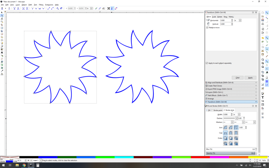
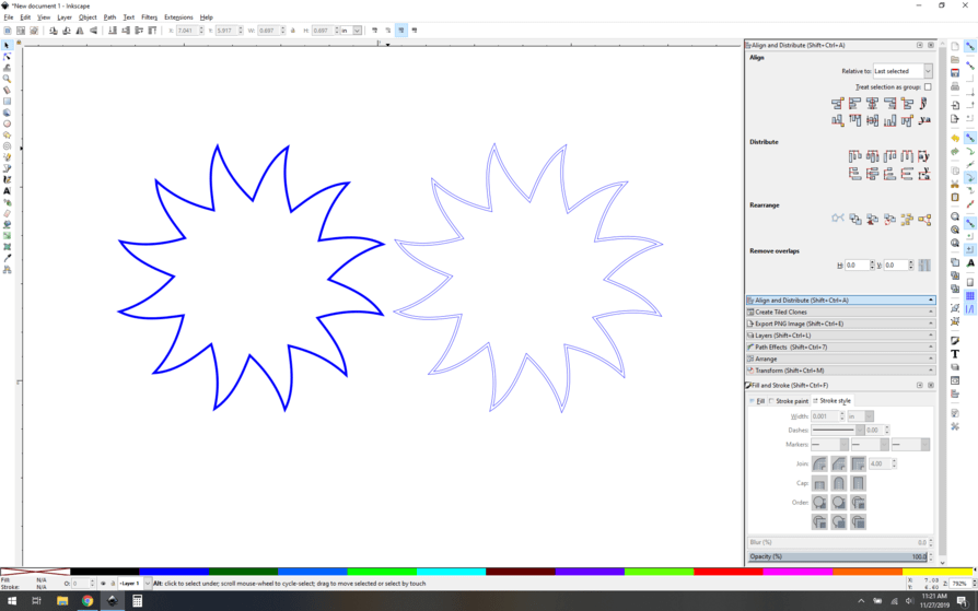
On the left, the original shape. On the right, the “stroke to path” result. You can clearly see that the path is deformed.

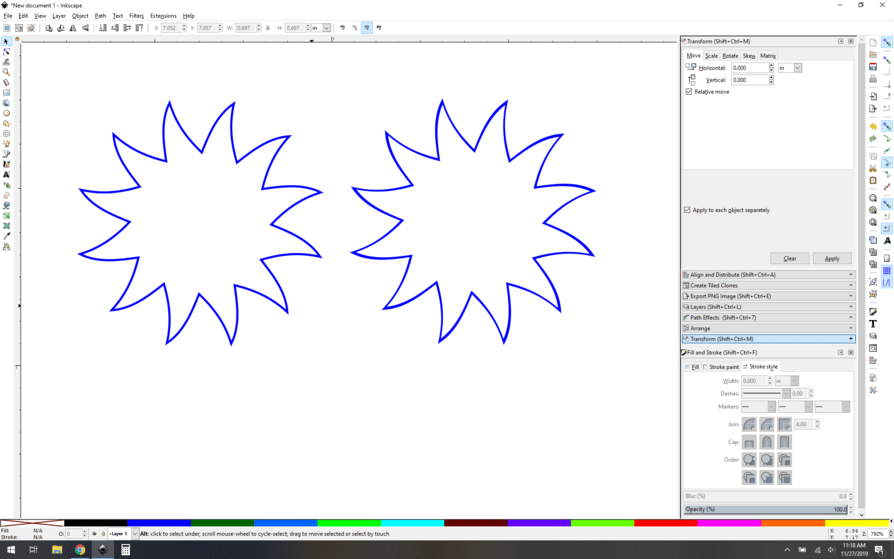
Here you can see the nodes from the original shape are bare minimum. Nice and efficient, but it’s a problem in this case, as we need dead-on accuracy for making our stroke-to-path kerf adjustment.

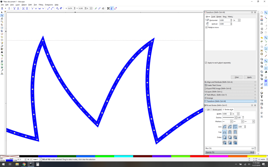
To add lots more modes, just select all the nodes and hit the “add nodes” button (Or hit shift-i) a few times. Each click will double your nodes, so use a little caution, it can get crazy quickly. Lots of nodes here.

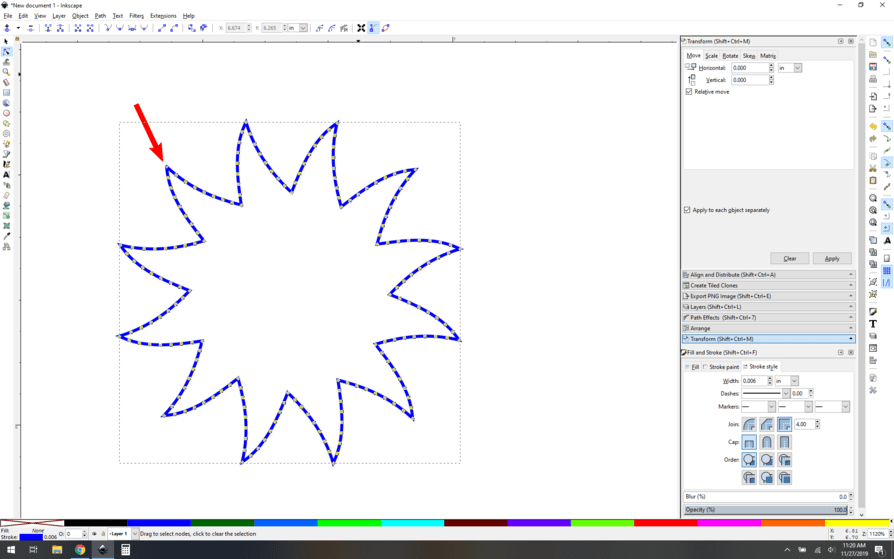
Now, take a minute to inspect your new path. You’re looking for any "weirdness’, specifically double nodes or the like. Notice that this point isn’t like the others, there are two nodes there and they need to be repaired for best result.

Click for details about my path repair method.

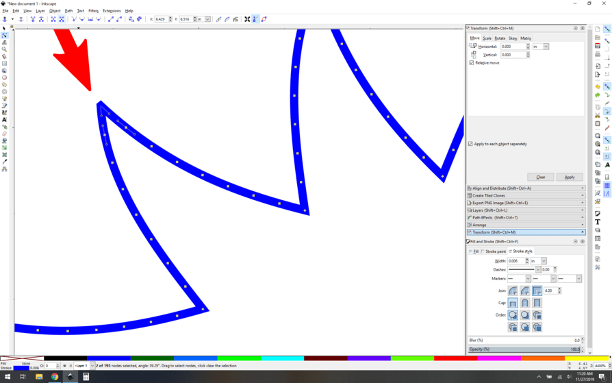
Starting here, I select the two nodes (note the count message at the bottom of the window):

Now click the “delete segment between two non-endpoint nodes” button [highlighted blue]. This will separate the two nodes and break your path…

Now click the join selected nodes button, which merges them into one node. Your point will look correct.

Now once you’ve inspected your path and you’re sure it’s correct, you can run the stroke to path action and get this:

That’s it. No deformation, no problem. You’ll have to adapt the technique to your own path, but basically, anyplace you have bezier sections can be improved with a couple extra anchor nodes. You don’t have to apply the extra nodes to your entire design.

35 Likes

:pray: fabulous work as usual. This is just in time to help on a complicated request I got from my Pappy. Thanks for sharing.

1 Like

Good tip! Added to the Matrix. :slightly_smiling_face:

1 Like

Is “stroke to path” Inkscape for “offset path” in Illustrator?

I think it’s more like expand a path, but @jules can tell you there.

No. It converts the “inside” and “outside” of a stroke to separate paths. If you had, for example, a circle drawn with a 2mm stroke, when you select “stroke to path”, you would have two paths, 2mm apart. You could then use “Break Apart” to separate them into individual objects.

Inkscape has Inset, Outset or Offset (dynamic or linked) for paths as well.

As to how to replicate in AI, however, I have no idea.

2 Likes

No, @evansd2 and @eflyguy are right, it’s more of an Expansion. (IIRC, Inkscape has a separate Offset path function, but I don’t recommend using it, because it has a really bad habit of smoothing the curves, throwing everything out of whack.)

I just kerf adjust using the line thickness in Inkscape.

1 Like

I can confirm that the adding nodes trick to improve path formation also works in Illustrator, I’ve done this. Use the Add Anchor tool.

3 Likes

For anyone here that can program in python a plea for a script that is done in Blender (in python) so worthy of a look. What it does is take a group of nodes along a line and take the number of nodes divided by the total distance and places them that far apart nice and evenly. I really miss that command in Inkscape and would love to see it there.

In Autocad there are two commands of Divide and Measure that will put the nodes in evenly that are also needed in Inkscape.

If already there I would love help in finding it.

In inkscape you can divide a path with an even number of nodes. Doesn’t do what you need? Extensions->modify path->add nodes… ? I feel like you probably know about this.

1 Like

Oh wait you mean you liked it in inkscape and want it in blender, not that it’s missing from inkscape. If that’s right, never mind :wink:

1 Like

I have not found that yet. I see I need more play time in Inkscape
This archived explanation is from when it was a separate add on but might spark some ideas.
https://archive.blender.org/wiki/index.php/Extensions:2.6/Py/Scripts/Modeling/LoopTools/

Struggling to follow - the Add node function in Inkscape isn’t what you’re looking for?

An interesting thing but no and only works on whole path, keeps adding but not spreading. The spiral making also has interest for limited use.

So here is an example of inlaying 1/8" walnut into 1/8" hard maple using this method.

There are a few more gaps the photo didn’t catch around the body. I forgot to flip the inlay image. That would help. It would probably help a lot. I know better and managed to forgot to do it twice as I tried two different kerfs. The tighter kerfed one (the image above) was set to .006". When that wouldn’t fit in the hole, I made one with a .007" kerf. When that wouldn’t fit in the hole, I grabbed the 24 oz dead mallet (a mallet where the head is filled with sand.) Both deer fit without any breakage. Here is a photo of the maple cutouts. Some parts of the antlers are barely there. You’ll need to zoom in as a lot of the antler is just shadow.

Note that this is friction fit only, no glue. I still have to sand and apply a finish. I did not mask either material as I knew I would be sanding.

To reiterate what evansd2 said in the OP you do need to check your image. When I did Stroke to Path in Inkscape the inside path had some sharp points where the outside path had rounded points. From prior experience I knew this would cause a gap and could wreck the fit. It was mainly the antlers and one node in the left ear. The hoofs and one knee also had sharp corners, but they were sharp in both the inside and outside path so I left them alone. Where the inside was sharp and the outside path was rounded I manually adjusted the “roundness” of the inside path. This meant manipulating individual nodes in the image that did NOT have extra nodes added. I then added the extra nodes and inspected. This is why I always save the source image. I did this three or four times until I liked what I saw.

  • I manipulated the nodes in the source.
  • Made a copy of it and then did a Stroke to Path.
  • Inspected the inside and outside paths.
  • Went back to manipulate the source.
  • Deleted the copy and repeat.

Having done this last spring without using this technique, and having become very down on the idea of complex shapes for inlay, I am now much happier. Now if I can just remember to flip the inlay image.

5 Likes

Went a bit crazy with the inlay for gift tags. The gift tags only need a name if there is some doubt as to who it is for. And some double as ornaments. The ornaments on the right are the learning ones when I was adjusting the kerf. A couple of the polar bears are held in place strictly by poly. I also combined engraving with some. I actually remembered to flip the inlaid piece for these. Life is so much easier when you do stuff correctly.

Isle Royal in Lake Superior is a double inlay. I needed a small needle nose pliers and my magnifying glass to line it up, but it slid in tightly.

Everything is made from maple and walnut hardwood, sanded to 220 and finished with Minwax Wipe On Polyurethane: satin finish. As these are meant to be disposable I didn’t work them that hard.

11 Likes