Who’s to say there isn’t a bluetooth chip in there that’s just not enabled? There’s a speaker that as far as I know hasn’t made any sounds yet…
6 Likes
I know. I got a little excited today thinking about it.
Giggle 
The motherboard/controller has what looks to be 2 (two) USB ports, but it is very difficult to see them.
4 Likes
This is same principal I used in the way mine works. Mine is obviously more customized to fit the gf though =)
3 Likes
Happy cake day @mad_macs !!!
1 Like
There isn’t one.
2 Likes
If there are USB ports inside, as someone has said there are, it would be possible to add one I guess, with software support of course . They have those tiny little ones not much bigger than the port itself.
Indeed, there are 2 micro’s on the front side of the controller board. At least one (the left side one) is an FTDI FT230X serial port for console access. No joy there for the purpose you are proposing. (Lots of joy there for other purposes ![]() .)
.)
I haven’t investigated what the other one is. If it is connected to the i.MX6 Solo’s EHCI, then I guess it would be feasible.
2 Likes
I had only heard USB ports. How come someone hasn’t done a full endoscope on their Forge yet, and looked at the nooks and crannies?
I’ve been kind of addicted to this guys reviews on stuff. He’s pretty funny and swears a bunch in Canadian. NSFW unless you are a longshoreman or oil rig worker.

7 Likes
Pretty sure they have. When warranties start to expire, the videos will probably start to emerge.
4 Likes
I was just looking at this and sketching out some designs. I think this would actually be fairly straightforward to make for the Glowforge. Wondering if @karaelena would be interested in sharing his F360 file? I’m also happy to design from scratch, just never hurts to have a starting point.
I make pens and it would be nice to be able to do this on the wood bodies. Are the drawings for these parts available? I do not have a cad program at present to be able to design my own. Any suggestions on an in expensive cad software friends?
Ken
I also make pens and have been looking for a rotary attachment also. In the meantime I am using a Chinese 1000 mw laser with a rubber band driven rotary drive to do engraving 360 degrees around the pen.
The project above was a prototype/proof of concept design.
August of last year I designed and built this.
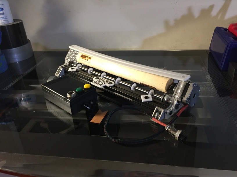


It’s basically an ESP8266 that ran a WebUI where you gave it the diameter and the distance to move. And either from the physical buttons on the box of the UI, you can advance the stock.
I made a template to help align the device with the preview in the Glowforges UI.
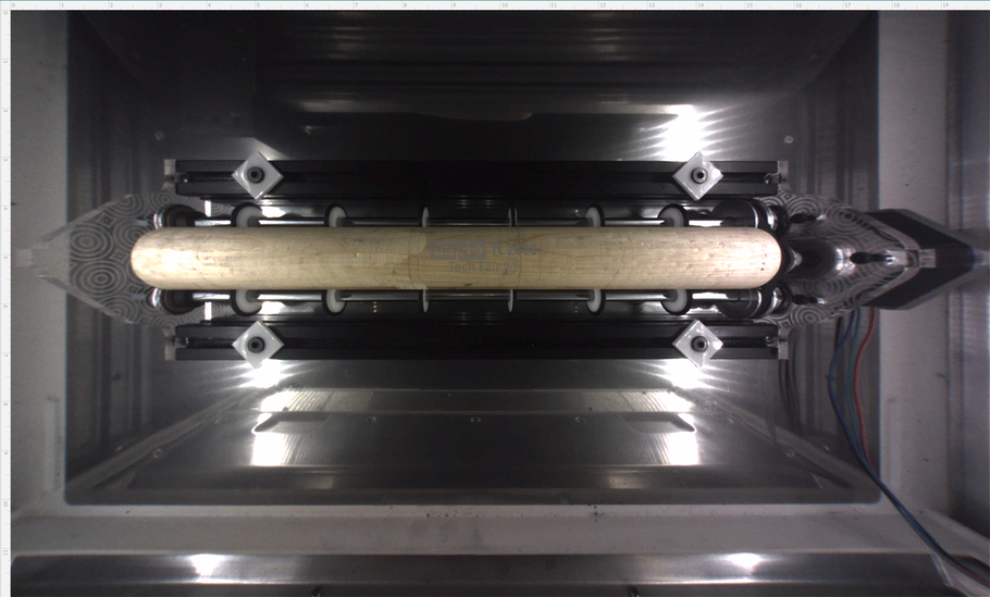
It worked fairly well until about December of last year. It seems Glowforge changed the way it does the autofocus ‘check’. When I designed it, I made sure the top of the stock was the exact same height that (I think Maple) Proof grade stock sat at (including the bed) so when it saw the QR code it was adjusted accordingly. But now, it seems to pick a spot that’s slightly outside of the area that needs to be engraved. And this is a curved material so it gets a weird reading and does a horrible job on the engraving. Even manually setting the height gives the same results. When I mentioned this to a couple people I know they argued/insisted that the value set will override the detection phase and in my case, it does not. When I measured the bed I used gauge blocks to get a pretty accurate reading and measured 5~6 sheets of the ply to get a good avg. of the height and designed the whole rig to operate and hold the stock at that height. At any rate, something changed and I have not worked on it since.
I plan to at some point revisit it and figure it out, but other things have come up. (Life things, Projects and other machines.) Stuff that pays the bills.
16 Likes
Any updates on this. Do you maybe habe an github for that so I could also work on it.
No updates and no github.
I got a couple messages about the rev. 2 of the rotary. Figure it would be better to reply globally.
The idea was to load a full bed vector into the UI. 12x20 with a ‘target’ outline of the device. Mostly to make sure its straight inside the machine. That’s what the white acrylic part with the slit is for.
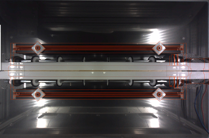
Then line up your vector in the ‘center’ of the work piece.
If you had something that wrapped around a material, I had a template gave you a guide line of where to place the vector, then you used that to split and overlap them on top of each other in different colors. i.e. red - 1st, blue 2nd etc… Cumbersome but with out direct control of the device from the UI there is no other way to do that I’ve found.
As for the control method, I had two, Via a webpage-
And two physical buttons on the control box. In the firmware I had to move 24mm forward and backwards.
And as for when will I pick this back up. Most likely soon. Currently in the process in another mod. Once that is done I’ll revisit this design and try to make it vertically shorter and slightly narrower. And find a better way for the focus height detect to pick a consistent point and have something there for it to pick up.
14 Likes
Will be watching the progress. Don’t know how long my Chinese 1000mw will last.
Awesome post, I thought I was on the Instructables site Have you motorized it yet?
I just ran across this thread – as I was reading it I was thinking to myself that this conversation sounds like every day geek speak at the local makerspace. 
I wish we were all local — can you imagine the fun and the amazing creations that would come from under one roof? A new techo version of an etsy-style store would blow out all competition. LOL. Seriously you all amaze me.
5 Likes