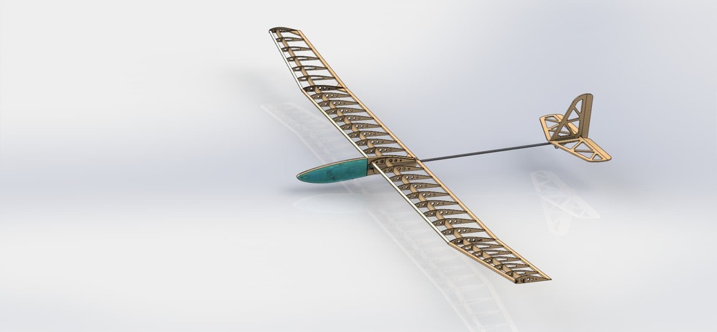
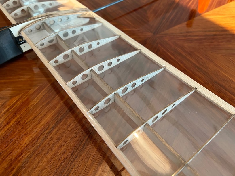
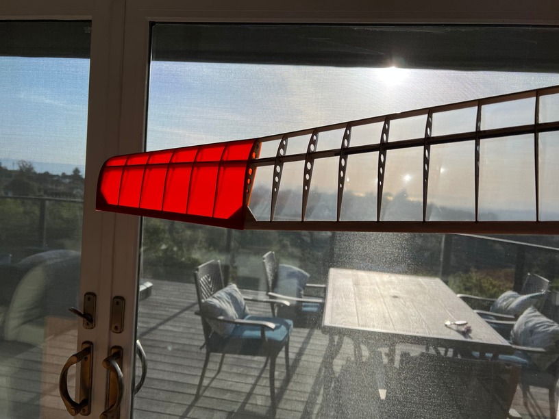
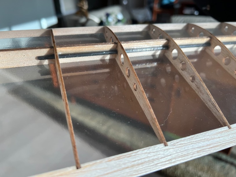
This project really started as a feasibility study. Could you make a radio controlled glider almost entirely from Glowforge cut parts? The answer is YES, of course. The model is constructed mostly from 1/8" and 1/16" balsa, which cuts very cleanly and quickly. Because of the accuracy, the model assembled nicely, with little or no adjustments needed.
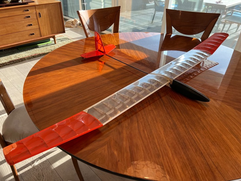
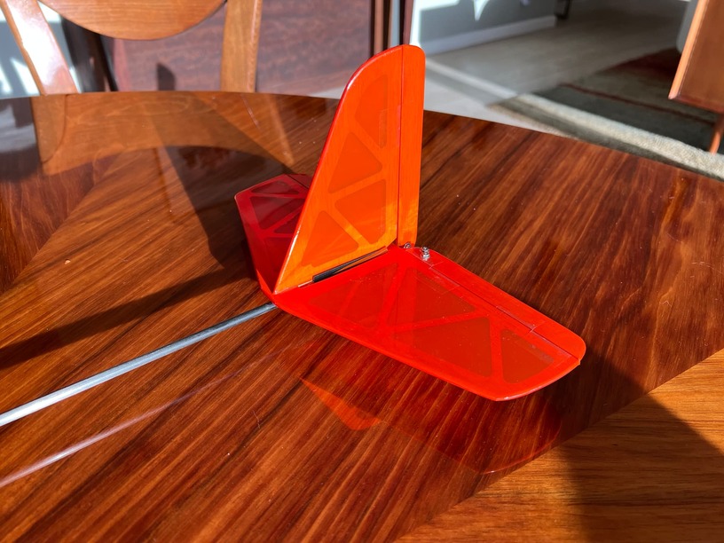
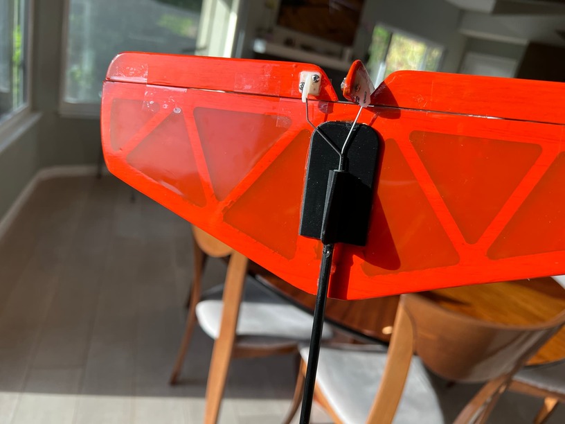
In addition to the balsa, the model includes just 3 3d printed parts (in black) and 2 carbon rods (one for the “boom” empanage, and one for the wing spar. It was covered in clear and translucent red Monocote.
The design was done in Solidworks CAD, and the faces of the various ribs, etc. were exported as DXF files and grouped together by placing them in a drwawing file, and again exporting the drawing as DXF.
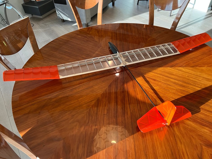
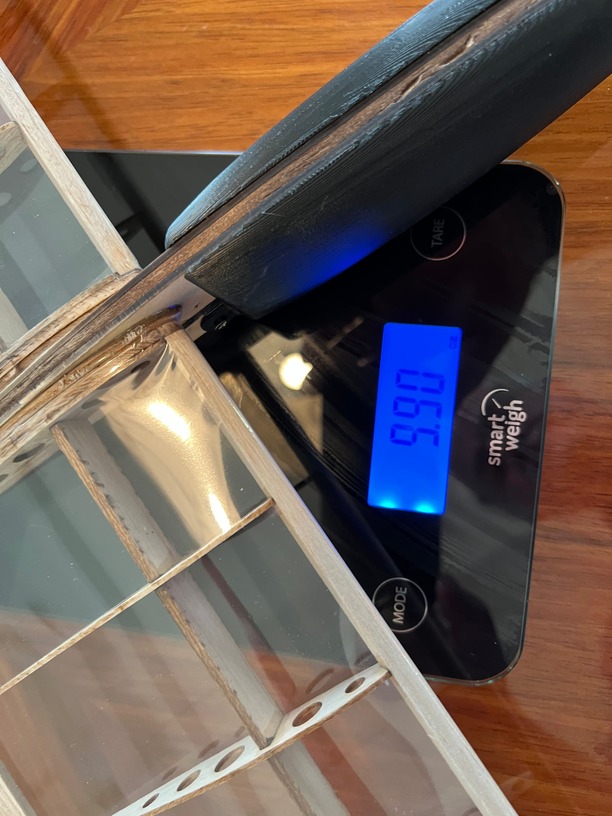
The model has a 62" wingspan, constructed in 4 sections, so each could fit in the Glowforge. Fully assembled, it weighs less than 10 oz. The radio is a Spektrum 6DX using 2 HS-55 sub micro servos, an AR410 receiver, and a 300mah battery.
I have not flown it yet due to the local winds, but will report back after the first flight.
I get a little gitty every time I see something nice for RC being done with the glowforge.
Very nice indeed.
I’d encourage you to share what you learned from this project in the tips and tricks section if you have any insights.
I read it wrong then. I thought the 1/8" was plywood (based on the last photo from above). I assumed the 1/16" was the balsa wood (because that is what I use).
Ribs are 1/16 balsa, spar is 1/8 balsa (ribs actually interlock to the spar for alignment and fit into layered notches in the 1/2" trailing edge stock). Nose area of the fuselage is actually a three ply laminate of 1/16" ply on the outsides with 1/8" balsa in the center, then cut as a single 1/4 laminate to retain the servos, battery, and receiver. You can’t see it in the pix as it is covered by the black 3D printed shell. I also used 1/16" ply for spar gussets where the wing is angled. None of the material is from GlowForge.
As a fellow SW user, I think the double-DXF process might be a little cumbersome. I usually just make an assembly with all my parts, get them arranged as needed, and then make a drawing. Once in a drawing, you can either export as PDF and cut directly, or if you want to specify cut sequence, use layers to create colors. Then use the automatic edge conversion tool to convert each part to a sketch, using layers to assign your colors. Then hide the parts to prevent double cutting and export as PDF. This also allows you to add text, engraving areas, and bitmap images in the same PDF.
It sounds like our workflow is actually similar. You import parts from an assembly and arrange them into a drawing. I select faces from the assembly/part and save as a DXF (no need to re-orient the parts). You create sketches of each part in the drawing then hide the parts, and I import the saved DXF files into the drawing and arrange for cutting (I also cut and paste for duplicate parts like ribs, etc.). You add text, images, etc. to the sketch and save as PDF. I add texts, images, etc. to the sketch, and save as DXF. We both upload to Glowforge and cut.
You are doing an export twice though, instead of once, and using a file format that can have scaling issues during import and export.
And no, I do not import from an assembly. I do all my layout in the assembly. That allows me to optimize cut paths by placing parts that can share a cut next to each other, doing multiple sheet layouts in the same file, etc. Using DXFs you either have to delete lines from the DXF imported object or you can’t share cut lines between parts, leading to longer cut times and more wastage.
Only once the layout assembly is the way I want it do I create the drawing from the assembly and convert the shapes to sketches if I need to, which is usually only if I want to control the cut sequence. Otherwise I just export the drawing as PDF. I think a PDF is a smaller file size, though it could be dependent on what the file contains. One huge advantage of using an assembly and drawing is that if I need to change anything the drawing automatically updates and all I usually need to do is re-export the PDF once the change is made in the layout. If I have to add a new part I will convert the edges of the new part if I need to control the cut sequence, but I don’t have to export and import and arrange again, just arrange.