Let’s say I make a design, and in that design, I assume all my material is 1/4" thick (0.25 inches).
I buy some actual material to make the design and use some calipers and find it’s only 0.22 inches thick.
What’s the best way to deal with this?
Off the top of my head, I would go into Inkscape (or another drawing program), groups all the elements, and resize the whole design to (0.22 / 0.25) or 0.88 or 88% of its current size. The overall piece would be 12% smaller, but in theory the design should still work.
I know I can also user parameters in Fusion for material thickness and then adjust those parameters and have it redraw my entire design for me. But let’s assume the design I have is just an SVG file.
What are the best strategies for dealing with this kind of thing?
I’m currently struggling with that a bit. I think I’m about to the point of just designing for the actual size (3 mm or 6 mm) and accepting that sometimes the slots are going to be a bit too large.
I guess it will leave room for glue.
Or we could just design for a slightly smaller size, and accept that sanding is in our future. Not sure which way is better.
Once i start getting some actual material in place, i will be measuring it carefully and setting up a Desk Reference chart with avg. nominal sizes by material/manufacturer. (I did that with papers and chip with the craft cutters.)
That’s what I’m thinking about lately when doing my designs.
I’m wondering if the “resize the whole design by X%” works in most cases. If it does work, should GF include that as a feature in the GUI?
Somewhere in the GUI, it would be nice to have a place to say:
the design has a material thickness of 0.25".
the actual material thickness is 0.22" (or the thickness is read off the proofgrade label).
Once we specify this, the GF asks if we want to resize the design to fit the actual thickness.
That way, one design could work with many different material thicknesses.
This will not work with all designs. Sometimes you need the parts to be exactly a specific size for the part to work. But it would still be a nice feature for most designs.
Definitely going to depend on the design. I’ve got a couple in the works where the only thing that I want resized would be certain slots for the equivalent tabs.
If you have to have the end product meet a certain minimum clearance, you can’t just resize the whole thing.
Trying to design for overall shrinkage starts to make things “complisticatered” quickly.
the only thing that I want resized would be certain slots for the equivalent tabs.
Exactly! I think you may need to either use a true parametric design (i.e. Fusion, onShape, etc.) or be prepared to manually resize the elements where it matters.
I would be very surprised if the Glowforge web app can ever do this given all the possible types of designs that it will be asked to cut.
Agreed – the use case that popped to mind was a wooden router bit / mill end holder. The holes in the top would need to remain constant, but the assembly tabs should resize based on the actual thickness of the material.
Fusion, SketchUp, Solidworks, etc. can handle this, but it takes a bit of digging into (and experimentation) to set up a useable parametric design.
I can’t imagine a case where I’d expect the GF plugin/gui to do this automagically, but perhaps that’s my lack of imagination…
There could be a way to partially incorporate the function if they wanted to, by making it possible to resize “only” elements with a specific line color or fill color or some other identifier that would be set up in the initial file by a designer. As long as we know the rule that “paths with pink strokes” will be resized by the “Nominal Adjustment”, and nothing else, then we can go ahead and design the affected slots with pink strokes, because we know those will change.
It’s really just “partial parameterization”. I design that way now - all affected slots are set apart with a different color of some kind and grouped if possible. That way when the time comes, they’re easy to find and fix quickly.
Might try to write an Action macro for AI to do it, if I get inspired. So far, it hasn’t been enough to justify it, but it would be fun to see if it could be done.
This probably isn’t much help, but I’ll often wait until I have stock in hand before doing a final design for a project so that I can design with actual thickness in mind. That’s for machined parts, but I expect that I’ll follow the same path for Glowforge projects. With luck, the Proofgrade material will have a pretty well defined and consistent thickness spec for acrylic, woods, and similar materials.
I usually do that with my own designs (for things I cut for myself). But I’m thinking more about designs I want to post on the GlowForge Design Store.
I’m thinking of something like the candle holders I’ve seen a few times in GF videos.
Someone who downloads that design might want to cut it out of wood, or plastic, or something else. And each of those materials might have a different nominal thickness.
I would prefer to not have to post 3-4 different cut files, one for each material. I’d prefer if the person who bought the design just specified “I’m using material X”, and the design automatically adjusts to the thickness of material X.
That should be pretty easy to do with most parametric 3D CAD modelers, like Onshape or Fusion 360. Seems like it would be harder to semi-automate in Corel or Inkscape but I haven’t used either too much.
The problem with scaling your design is that your overall piece is now the wrong size. For example, if I’m building a box and I want the interior of the box to be 6"x6"x6", then scaling the design down to match the actual material thickness is going to make the interior smaller. The best option is to measure the material and design for that size. (parametric design seems to be the way to go here)
I agree, the box size is now not “as designed”. But perhaps it’s okay that the box is only 5.5" x 5.5" x 5.5".
It depends what you are designing. If it’s a box to hold something specific (like a deck of Magic Cards), then you need it to be a specific size. If it’s just decorative, then you don’t.
My question pertains more to designing something that’s going to be cut out of several different materials. And I don’t yet know the exact thickness of those materials. And the person who is downloading that design does not have any experience with parametric concepts. They just want to cut my design in their material.
The trouble with that is you only want one dimension of that slot resized (to compensate for the thickness of the tab) so your slots would need to be 4 lines instead of a box - the two sides would be your pink resize color and the two lengthwise lines would need to be a non-resized color.
With all of that added complexity either manual adjustment or biting the bullet and making a parametric model is probably equally time consuming.
Once you go solidworks. You never go back. just saying. I have a design controlled by a excel sheet. Change the cell named “slots” and everything works. (within reason)
As a disclaimer, my job owns my license. I don’t know if I would buy one myself. Especially not as a hobbiest. So in that regard I definitely understand the challenge. And have worried what I will do if I lose access to solidworks somehow.
If this doesn’t get implemented the store has potential to become a real mess.
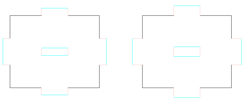
I like @Jules suggestion about making parameterized lines pink (or whatever). I’d also add a second color, say cyan, that denotes which lines are also moved when parameterized lines are extended/truncated.
(Assuming the Glowforge software is capable of detecting which lines are connected…) The ends of pink lines attached to black lines would remain fixed and the other endpoint would be moved. Cyan lines attached to endpoints of pink lines would move. The endpoints of pink lines that aren’t attached to black lines would expand equally in both directions.
Hmmm… endpoints of pink lines attached to non-cyan lines would also probably need to remain fixed.
Of course, we’d probably need at least two parameterized colors and at least two “along for the ride” colors for the two main kinds of action a lasercutter can take: cut and engrave. Would we then use even more colors for scoring and different engrave depths?
Maybe the Glowforge software could detect gradients and use those for resizing slots/tabs.
Do Illustrator/Inkscape have parametric features? Using colors is a kludge to allow non-parameteric software to be used to make designs that would benefit greatly by dynamic adjustability.
–edit—
Shoot, I realized that I may have misinterpreted the original question.
@polarbrainfreeze, were you asking about what you could do to make a design work with the Glowforge software or were you asking to find an immediate solution to this problem? I assumed you were asking the question so that you could preemptively modify your designs now so that transitioning them to the Glowforge store would go smoothly.
Maybe it’s because I’m still learning Fusion. But I’ve built things using user parameters to solve this exact issue but when the model gets very complex it’s still a pain to manage in my experience.
I like the idea of http://openjscad.org however I don’t like using it very much (even as a computer scientist). We need an easy way of sharing and modifying parameterised models.
The problem is that the svg does not contain the constraints that are obvious to you. A small thing like the red and cyan line being perpendicular to each other is not information contained in the svg. Now an intelligent piece of software might be able to infer some of the constraints but imagine that you want a curve to be relational to material thickness of similar. Gets complicated very quickly.
Also common ruleset for lasers acting as printers (to a computer) is that color defines laser power and thickness of line defines vector cutting vs raster engraving. This is a hack on an existing protocol but gets the jobs done and ensures compatibility with a lot of software/hardware.


 just saying. I have a design controlled by a excel sheet. Change the cell named “slots” and everything works. (within reason)