I think you see issues like that when there is an open shape and the software attempts to close it.
Keyboard shortcut in Inkscape Control+5 will put the view in outline mode, and you can zoom way in to see if that’s the case.
If that’s no help you could zip the file and drop it here. Someone will help check it out.
Hi
Yeah that is the case… unfortunately control plus 5 hasn’t worked. Il send the file if I have no outcome soon. 
Edit: is there anything I could do in AutoCAD to resolve the issue?
If you can turn on nodes and look at the paths, I think you will see open paths on the top and bottom edges.
Otherwise, you are looking for a function along the line of ‘Close Paths’
I’m sorry you ran into trouble. Unfortunately, our team doesn’t have expertise in AutoCAD, but could you please send us the .svg file you’re running into trouble with in Inkscape? We’ll be glad to take a closer look.
Hi
Yeah I checked for nodes but there are none open. Not sure how to deal with closed paths.
designersdeck.svg.zip (13.9 KB)
Thanks. This is the file.
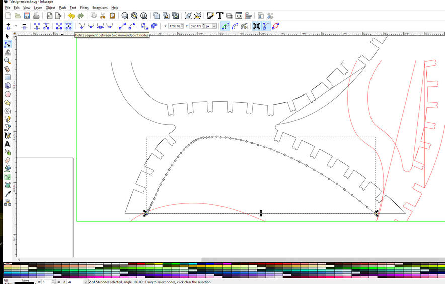
In inkscape you need to go in line edit mode select and break the straight line thus
and In edit you can make the design fit the page and eventually get this, That you can DL as an SVG

Oh thank god and thanks to you. 
I didn’t understand the last bit about fitting page?
I’ve basically made that rectangle in AutoCAD to fit the gf.
In Inkscape in the Edit pulldown most of the way down is “Fit page to selected” and if you have everything selected, it will use that to set the page in height /width and usually zero/zero in the lower left corner.
But before you start it would be useful to go to ,Shift+Ctl+D> and make sure all the settings make sense. Though if bringing in an Autocad drawing I would use the “fit page” first. Also Autocad splines come in very dense in nodes where polylines do not I would make a series of straight lines and then have a lisp run fillet poly a few hundred times starting with a minimum and stepping up in radius each time. in that way all the curves were as large as possible but each tangent to both lines. This would produce the fewest nodes.


This is what came up on mine, maybe cuz it’s a Mac… not sure. I couldn’t see it in edit. This is properties.
Also I’m not too experienced in either programs so wouldn’t be able to do detailed stuff ![]()
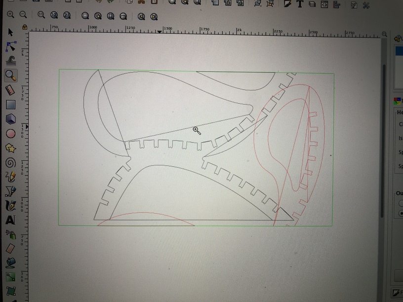
Just noticed there is one other problem though… after opening up in Inkscape the layout seems to have changed…


That first Image is correct. Check that all the quantities are in Inches, the scale is 1 to 1, The default sizes are not what we use soI make the page size 10 high x19 wide but it rarely ends up as that. however It lets you size to the space available, and when using Align <Shift+Ctl+A? it is convenient to use that with page as a basic start
I set my Grid to 0,125 inches with the major lines at 1 inch but your snap usually very low unless it is mandatory (like making a ruler)though for guides set the snap high as they would not be there if you did not want to snap to them.
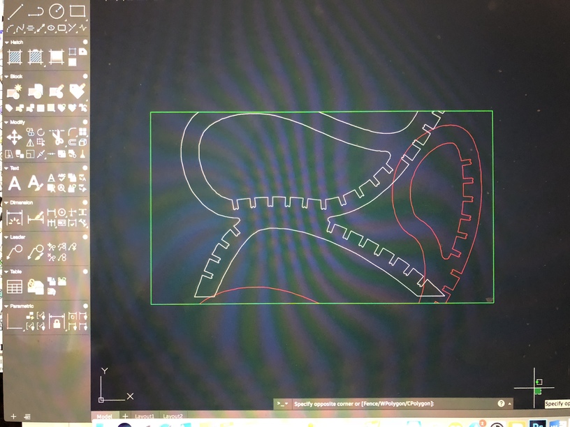
The first image is from AutoCAD as that’s the one I know how to use unfortunately when I got the gf I couldn’t save and open the dwg or dxf file in gf so I was recommended to open and save as svg file in Inkscape however it’s chnaging the file. I’m working in mm in AutoCAD.
I’m afraid you have more than one issue with the file…there are quite a few places in it where what looks like open ended single line paths have been closed into shapes that are going to burn twice as the laser follows the path…you can see one of them here if you zoom in:

Here’s the problem that you’ll run into trying to repair the file. The issue with exporting DXF files from some of the CAD programs is that the lines come across as unconnected short segments, and depending on which program you pull them into to fix them, you can get different results. It looks like Inkscape is closing the open paths, and not necessarily in the way that you want them closed. It’s a recognized problem in dealing with some of the CAD files.
So what you need to do to fix it yourself, if you want to keep using AutoCAD for design purposes is:
- Always set your artboard up in AutoCAD to be exactly 508 mm x 304.8 mm to start with, and design on that.
- Set your artboard size in Inkscape to be the same. (Hopefully that will get rid of any resizing issues/variances. If you work in mm in one program, stick with it across the other programs you use for conversion.)
- While you are designing, if you can use the Polyline tool (or whatever the CAD equivalent is) it will reduce the number of open-ended paths that occur. Close whatever shapes you can.
You can try joining the open segments in AutoCAD if you are more comfortable with that, or after you have opened the DXF file in Inkscape, you will need to connect the open segments. (And just importing the CAD results into Inkscape might be closing them, so that would entail breaking them first and then reattaching the segments correctly. It’s going to be four times the work.)
You might be better off saving the original CAD file as a PDF if you can do that. It might work without further processing. (Don’t know for sure because I don’t use AutoCAD, but I recognize what is happening with the file. I’d give that a try first to keep from having to rework the whole thing. See if it works to export the open segments without closing them.)
The Glowforge interface can handle open paths for cutting and scoring, which means set a stroke color, but no fill color for the shapes. If you try to engrave them, it’s going to try to close the shapes, and you are going to get some strange results.
If you can upload the original zipped DXF file here, I can try to take it into Illustrator and see if there is an easier way to fix it. The SVG has already been corrupted.
Thanks for your reply… the double lines you mentioned are also shapes being automatically closed by Inkscape which has been solved by deleting segment between 2 non endpoint nodes as rbtdanforth explained but when I open the AutoCAD file it changes layout. As for setting up the page… I’m only opening and resolving the file to be opened in gf. …Unless I have lines to delete.
glowfrg community.dxf.zip (32.1 KB)
Sorry I forgot you asked for this. Thats what happens when you have 3 babies:sweat:. Thank you very much for your help.
As the mother of 3 closely-spaced children myself, I’m amazed you can type a coherent sentence! ![]() Mine all survived to adulthood and are now in their 30s, and I’m still relatively sane – so hang on, there’s hope!
Mine all survived to adulthood and are now in their 30s, and I’m still relatively sane – so hang on, there’s hope! ![]()
Oh I wish I do… especially the fourth one being their dad… oh and there I’m serious. …lol don’t know whether to laugh or cry
Haha, I had the same problem! Eventually got smart and traded him in for a more mature model. ![]() (Kept the kids, though. THEY grow up!!!)
(Kept the kids, though. THEY grow up!!!)