the issue is i don’t know what the scan gap is on the GF or how to set it. or how to measure the LPI in equivalent of scan gap to determine the proper LPI to use these scripts at. they were built for non-GF machines that have scan gap settings.
So, if I understand this correctly, the scan gap will be .008" (.2mm) at 125 LPI (i.e. no overlap of the beam). At 270 LPI, the scan gap will be .003" (.0762mm) and the beam will overlap 62%., at 450 LPI the scan gap will be .002" (.056mm) and overlap 72%.
Doesn’t the scan gap refer to the distance between the horizontal rows? And a tighter scan gap could result in some overlap depending on the width of the beam? I don’t think there is a single scan gap, it should be a configurable setting.
I’m not sure this is right either. I’m trying to make sense of it. The way I read it is that the scan gap is the distance between the middle of each horizontal row, not the edges.
ok, a little chatting w/@jbmanning5 and some info he had, along with a memory from some sleuthing around earlier, and i went back to this page.
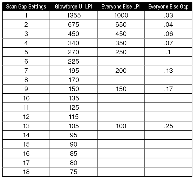
which got me to this table.
then, from there, i married the table above from a more traditional look at scan gap. there’s some overlap, and hopefully i can use this to do things comparably and try to marry recommendations from other laser cutters to how i’m engraving the scripted photos.
life might be easier if GF identified the scan gap on the same kind of scale that other laser cutters do, but the rest of the numbers aren’t really comparable either, so…
I don’t know that it would be entirely academic; ultimately, you can calculate out the optimal resolution to engrave a specific file at (or, the optimal resolution to save a file at). Somewhere in the processing, either the laser is going to be tossing data, or repeating (or interpolating) data to achieve the final engrave. If you know ahead of time the resolution that you want to engrave at, you can save your file so that the data loss or data interpolation is limited, which should give more accurate results.
the problem we sometimes have with the GF is when you talk with people using other ecosystems and they talk about their processes and there’s just no easy way to convert their settings to making something on the GF.
i’m running into this exact issue right now, which is why i went through this exercise and will do some more testing.
the “some dude with a lazer” scripts i mentioned seem to take a lot of guesswork out of converting a good photograph (so, like with everything else, GIGO) into an engraveable photograph.
for right now, i was able to use it a few times in paintshop pro before my free trial expired.
BUT
he’s in the process of writing them for photoshop. and THAT would make me very happy, since that’s my real happy place for image editing (and i wouldn’t have to buy something new). and some of the stuff he’s been engraving looks amazing. especially with paint on top of ceramic tile.
FYI, if anyone else is interested in the scripts, the original post has a link to his facebook group. from there, he has posted the paintshop pro scripts for free.
he’s been rewriting them and is going to put out some photoshop scripts, but those he will be charging for. he made the PSP ones for himself and shared them. enough people have clamored for them in photoshop that he recreated and tested, so that’s why he’s going to be charging. he said something like $15-20.
So the while LPI thing versus DPI, can be tough to wrap ones head around (like getting into DPI, PPI, etc.)… resolution is always difficult to convey in this regards, in my opinion. Technically, in commercial offset printing, you have LPI * 2 = DPI
But, if you just plug in the standard formula (1 / LPI) * 25.4, you actually get very close to what your chart above shows:
Scan Gap
LPI
Scangap from LPI (mm)
1
1355
0.019
2
675
0.038
3
450
0.056
4
340
0.075
5
270
0.094
6
225
0.113
7
195
0.130
8
170
0.149
9
150
0.169
10
135
0.188
11
125
0.203
12
115
0.221
13
105
0.242
14
95
0.267
15
90
0.282
16
85
0.299
17
80
0.318
18
75
0.339
Actually, I hid some data in the first table. This one has if you converted out the LPI to DPI, and I also converted the LPI scangap data to inches, because that makes more sense to me (even though it’s not the standard)
and just to make it worse, that is highly simplified. you’re really more interested in linescreen than LPI, which is slightly different, but not as simple since every press (or plate maker) has a different linescreen.
but thanks for building that table w/the standard formula.
it may be a few days until i get to play with this more (new dog arrives tomorrow, probably not spending much time in the upstairs office for her first few days). but once sean makes his PS scripts available and i have a little time, i’m going to start engraving more test photos.
LOL!
Can’t tell you how much material gets wasted playing trial and error on this thing. I’ve got a couple hundred worth of stuff I’m not even going to touch until I get snapmarks…
so this looks like a really good explanation of scan gap and why it matters, especially when setting the DPI of an image in an image processing program. i now think i understand how scan gap works and why.
later this week i need to look at @jbmanning5’s tables and convert some images and burn them.
for now, it’s play with the new dog time. especially since she’s been a little “velcro” on her first night so far and i don’t want her going up the stairs yet (still has stitches from her spay).
I should note the script doesn’t convert to 8-bit at any point, which is required for converting to bitmap.
In Photoshop, resized, but didn’t resample, down to 6x4 (so about 1000 DPI).
Decided to run the tests at 225LPI, ran the Photoshop dither script with default settings for 2 different instances, one at 225 DPI, one at 450 DPI (LPI * 2). I cropped them as similar as I could for comparison’s sake, but I didn’t get it perfect.