A while back I was wondering why we don’t have a pulses-per-inch setting for vector cutting. If I understood the answers correctly, it’s because our laser power can be continuously modulated and we don’t need it.
Well, I wanted to see what would happen if I could somehow fake the setting by cutting a zillion tiny line segments. Some materials are challenging to cut cleanly–looking at you, PETG–so I figured why not try something new.
The short version is, the Glowforge does not handle a microscopically segmented line as you might expect.
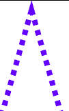
Here’s the sample object, a 5 pointed star that is about an inch tall. The lines are made of line segments at what should be 300 segments per inch–so, this should simulate a 300 PPI cut at my indicated Speed and Power.
But when you cut it, instead of zipping along at the speed you set, the head moves very slowly and you end up with more power put down than you expect, and a much bigger kerf than if you cut a normal line. I guess the motion planner is accelerating and decelerating to every segment? In any case, it did not move along at full speed making many closely spaced cuts as I had hoped it would.
If you want to experiment with this technique, you will need to convert your lines to a series of lines and spaces. Someone mentioned a way built in to Inkscape to do this, but I didn’t dig in to it. In Illustrator 6, the easiest way I found was to do it this way.
Select the line you want to make dashed
Use the Dash tool to make your dashes and spacing at whatever tiny fraction of an inch you need, like .005 in
Set your Stroke width to .0001 pt
Do Expand… and select Stroke. (Normally this would turn your strokes into filled shapes, but in this case, the stroke is so thin Illustrator chops it up into line segments instead)
Change your stroke back to whatever you like for visibility
(I suppose this might also be a good way to make a series of slits for leatherwork.)
You can accomplish the same thing with a Pattern Brush and Expand commands but I found this quicker.
If the laser is going between two points it will start from stop and end in stop.
It would be incredibly tedious but if you had along series of points in a single line and turned the edge off at every other joint I think that the GFUI would see that as a single line with the laser turning off as the head continues and back on again when the line is there. I frequently do this to cases like a rectangle with 3 sides on and one off but as there is a sharp turn it still has the same issues.
For a series of slits or holes to sew leather pattern on a path is good. By making the top piece of the rectangle turned off only the rest is used as the path. In another place I wanted matching parallel sets so I removed the top and bottom so both sides worked at once.
So in inkscape: setup your dotted path style. Use the menu item to convert to line segments. Select all of the new segments and combine them, now you have a single path of disconnected segments. Should do what you’re describing, but node order and the GF pathfinding software might still conspire to screw you up.
One thing I have learned over the years is that computers always do exactly what they are told. How to tell them is often an issue, and it is easy to have things different than you think but they never make their own random decisions. Starting there eliminates the majority of the conclusions the average computer operator leaps to.
Particularly with open source the programmer is out to solve a problem they are having with a method and description intuitive to them and not vetted and psychoanalyzed. Looked at that way it can be much more intuitive.
I used to teach “Intro to DOS” classes, 'way back when. I used to tell my students that computers, like little brothers always do exactly what you tell them to do, but not necessarily what you MEAN. Like when one of my brothers (not @timjedwards) was blocking my path in our downstairs hallway one time, so I told him to move, and he started waggling his arms and head and jumping up and down.
My computers have always loved doing that to me… <3
I wish the motion planner would overrun the end of cuts and turn the laser on/off instead. That would stop the corner burn marks and heavier burns at the end of lines.
I just tried this in AI CC2018. The smallest I can set stroke is .001 pt and the smallest I can set the dash is .01pt. Expanding these still gives me tiny little boxes, not line segments.
Huh! Maybe there is some place I have different settings?
I just tried again and it still works for me.
If you didn’t try typing in the values, do that instead of arrows. When I type in .0001, the Weight field DOES show zero… but, leaving the object selected, I can still do Object->Expand, then bump up the weight, and I see segments.
That post I linked to says that what you have is a very very skinny closed path rectangle. I wonder if you’d get (basically) double-passes if you tried to score your dashes.
I don’t think the post is correct. If I zoom in allll the way, and switch to the tool that lets me grab single nodes, I see only 2 nodes for each segment. If they were truly rectangles, I would expect to see 4 nodes.
If I grab a node and move it around, there is no node under it. As far as I can see, these are true lines.
When I tried to cut this thing I did not get the results I expected, though, and I have no idea how the GF actually interprets this file. I just know the head was moving very slowly and the cut quality was very poor.
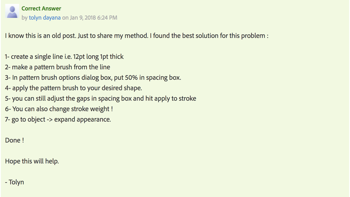
I think so, the “correct answer” looks like a pretty fair workaround for getting un-expanded dashed lines. Custom brushes are an incredibly powerful function that get overlooked by a lot of users.