I really like this idea. I might have to try and work it in to some of my designs. Link includes downloadable plans.
https://tltl.stanford.edu/project/universal-snap-fit
44 Likes
Bookmarked. Thanks!
2 Likes
bookmarked that and downloaded the files, thanks for the information.
2 Likes
Very nice. Always love seeing how others have solved a problem and then comparing.
3 Likes
rad. thanks for sharing!
2 Likes
Interesting design, I wish the files they released were better.
The SolidWorks files are not intelligently parametric, instructional use only, and have odd texture mapping. Also, there are several non-functioning files included in the ZIP file. The files do not seem to be “versioned”, which will make determining whether you have “new” or “old” files difficult.
6 Likes
nice find! also bookmarked.
2 Likes
I agree the files have some issues, but it a good starting point.
Once i’m home from vacation i will to rebuild a parametric version in Fusion.
I’ll post the file here for anyone that wants them.
10 Likes
Looking closely at this design, I don’t think it’s as clever as its complicated shape suggests. First, it is definitely not material thickness independent (they supply different designs for different material thicknesses). In other words, something made with the 3mm template will only work with 3mm material. If you want to cut that same thing out of 4mm material you’re going to have change all three parts of every snap to accommodate.
Also, can anyone explain what the two little leg things of the male side are supposed to do?
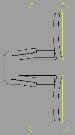
At first glance it looks like they’d help with alignment, but even with a kerf of 8-thousandths they wouldn’t even make contact with the female side…
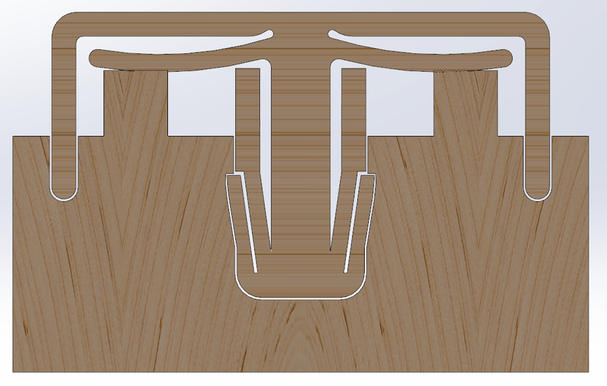
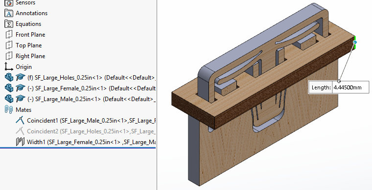
Actually, it seems like much of the snap won’t actually make contact. (the above image was made using the “large” “0.25” files (which wheren’t actually 0.25 inches thick, by the way)
I dunno… sorry, I know comments that veer to the negative aren’t appreciated on this forum, but I think this design may have room for improvement.
I might have to do a test cut on my laser today. If so, I’ll actually cut one and see what happens…
12 Likes
That might be a kind of little “dog bone” to enable use in acrylics. (Keeps it from splitting.) I think. 
Oh, whoops… never mind…you weren’t asking about the dip in them, were you?
3 Likes
I would hope the atmosphere of the forums isn’t anti-negative. Well, not anti-constructive criticism at least. Which is absolutely what you are offering.
My best guess for the side bars would be structural support. Something you can hold while manipulating the clip so you don’t break the actual critical components. And possibly a little bit of security against damage while in place on a moving component.
7 Likes
You suck, and your stuff sucks =bad
I’m not sure if this is the best way to handle this, what about… =good
So yeah, at least one of us (me) appreciates constructive criticism.
7 Likes
Sounds to me like you are just problem solving. I’d love to see how the test cut goes. Always interested in improving an idea.
6 Likes
These are good questions. It does seem to claim that one of the designs will work with variable thicknesses of material. So small would be would be say 2.5 mm to 3.73 mm. Medium would be 3.75 to 5 mm and large for 5 to 6.5. Perhaps universal is not the best word but adaptive sized fasteners better.
It looks overly complicated but each part must must have a purpose. I would hazard that the side wings are to prevent lateral movement in the clip. Since the central tab alone would allow for lateral movement. I’m not very good at imagining force vectors in models.
5 Likes
Alrighty, I cut a couple sets out and recorded a short(ish) video, which I’ll post below. (Please ignore the sniffles, I’m just getting over a lil’ cold.)
Most of the rest of what I write here can be gleaned from the vid, but I’ll reiterate a couple points for anyone who can’t/doesn’t want to watch 5 minutes of video…
It works. Can’t nobody say the design doesn’t work. For some applications it’ll work very well, I think.
The “legs” (which I apparently think is a catch all term) that I highlighted above seem to aid in resisting radial torque (I hope I used that correctly; I mean “twisting”). As a clip, I’d say the male pieces would work equally well whether they’re twisted slightly or not, so the outer legs probably aren’t necessary for that job.
The “holes” piece has a fair amount of play after all the pieces are assembled. It has much more play than a simple close-fitting tab and slot, in my opinion.
Some possible improvements…
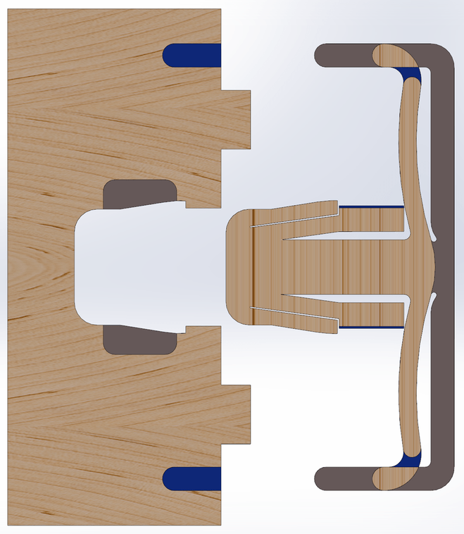
I hope the colors make sense.
Blue = added material
Gray = removed material
20 Likes
Thanks for taking the time to post this! While I don’t see this being too useful on small projects, The outer “legs” could be made larger with some interesting potential for added decoration.
6 Likes
Thanks for taking the time to do this - very informative concerning this connector. Would be interesting to use in some sort of construction where the female slot was sandwiched between two panels. That is, once connected it would not be removable ( no access). Or if this could be used somehow as a “puzzlebox” connector where something would have to squeeze or force the two locking legs in for the piece to be removed or freed… hmmmmm .
7 Likes
Thanks for testing these @Hirudin.
I’m a little disappointed with the amount play they have. They might work well in the right situation, but I agree that tabs and slots are better in most applications.
7 Likes
Thank you so much for trying that out and making a video. I agree, a bit too much play but may be useful for some applications. 
5 Likes
Are they intended as single connectors or as part of a line/array? Because if the latter, the effect of the play might be reduced once everything is assembled. And having some play initially would certainly help with assembly.
4 Likes