I delved into a part of Fusion 360 I had not tapped before, and spent some time scratching the surface on Parametric sketches with user parameters.
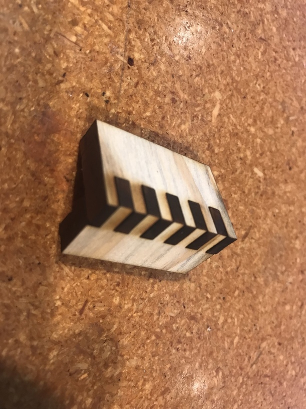
A little maths and some good luck, I think I have a working tab generator that compensates for Kerf.
So far it ONLY generates the fingers based on how thick a tab you want, how many tabs you want, how thick the material is, and how much kerf there is. Based on that it will generate a series of both sides of the joint.
The flashback is a function of using non-PG material, and possibly the settings you’re using. You might open a thread in Beyond the Manual about getting some help with that. I don’t think the K40 tray will improve things (aluminum is the cheap stuff and usually works worse).
Agreed. I was going to run further tests, but I think I can confirm the Aluminum tray is no improvement.
The comb is much thinner, so I thought that would help. For some reason ( probably less delivered power) I didn’t have problems with flashback on the K40.
It might be just me, but i have tried making a box from every resource here ( except inkspace ) and not a single one has actually fit together. I might be doing something horribly wrong, but I have no been able to sort out what exactly that is. I have been attempting to make a design for a 4.5in x 4.5in x 4.5 in box and absolutely every one of them has failed to fit together. The teeth just don’t line up on all the sides. It’s quite unfortunate. I’ve wasted so very much material on this so far.
What material are you using? How thick is your material measured by calipers without the mask? How tight do you want it to fit together? I ask, because with that info, we could generate an svg and tell you how we did it.
I have been using proofgrade acrylic. I am away from home at the moment so i don’t have the exact caliper readings for the measurements on hand, but I believe the material is around 1/8in As for how tight I want it to fit together I am trying to make a box that could stay together without glue or other adhesive so the fit should be pretty tight. A generated svg would be absolutely wonderful, but any pointers on how to adjust for things like kerf ( I have been doing a lot of reading to try to get this figured out ) or how to design tabbed boxes without using cad programs would be even more beneficial in the long run. Thank you for your help.
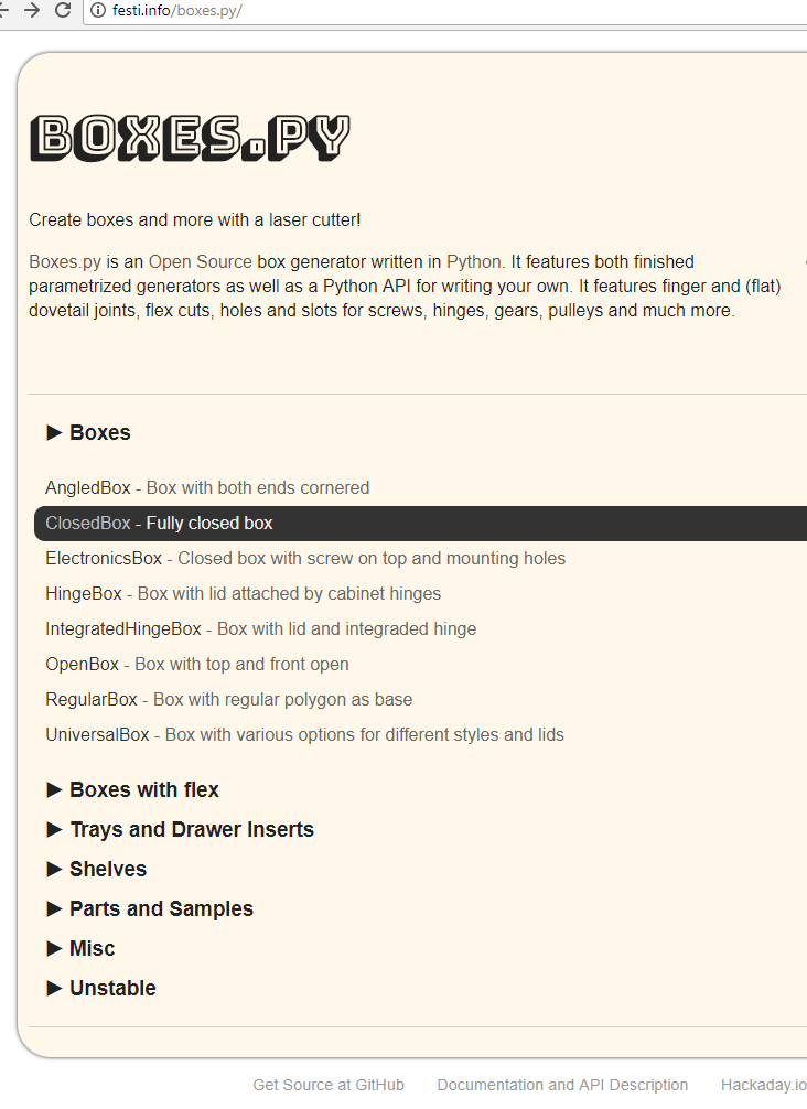
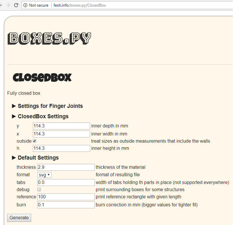
For acrylic you’re going to need an exactly measurement. Not a lot of give. I have had the best luck, fwiw, with festi. The defaults work pretty well, you just have to throw in the material thickness.
I agree with @paulw. Acrylic is going to be tricky to get press fit to work because it is stiff and brittle. Too small it’ll break during assembly, too big of a gap and it won’t hold together. With the plywoods, you can encourage it to go together with a mallet and it’ll give a little without breaking and then hold tight.
I used the calipers and measured my sheet of Proofgrade clear acrylic and it is 2.90mm thick.
I set x, y, h and thickness to the 114.3 mm (4.5 in) and 2.9 mm respectively. The rest are the defaults. When I was trying this out the first time, I was using draftboard and I did a little 50mm x 50mm x 50mm box first (2 in cube) since that’s less material. Also, I took the resulting svg and loaded up into inkscape to make little finger joint testers.
The default kerf setting here (“burn” in festi’s lingo) is 0.1mm which means that in Inkscape the fingers will overlap by that amount since it’s expecting the laser to burn away 0.1mm worth of material. The real kerf is going to be closer to 0.2mm so this might be too loose, but I think it’s a good place to start.
You can also measure the kerf by cutting out a square of a known size and see how much bigger the hole ends up being.
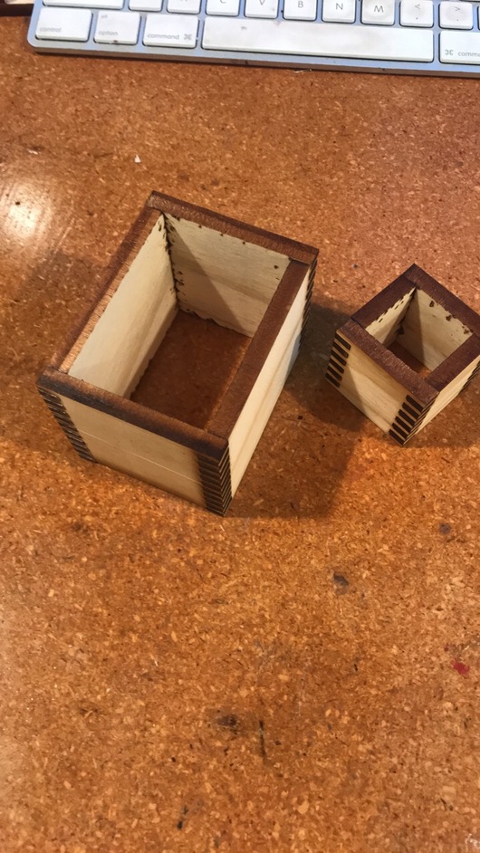
I ran through the above steps with 25mm x 25mm x 25mm (1 in cube), generated the svg and opened it up in inkscape to center it on the page and delete the reference rectangle. This is the result:
For my cheapo BB it makes a very nice press fit. Albeit I lie to the program and tell it that the material is 3mm when it’s really 2.9ish. (For PG it makes a looser fit that works fine with a thick CA glue.)
I had been using boxes.py 's default settings to make tabbed boxes and were a tight fit but worked. When i tried to make a Typetray (http://www.festi.info/boxes.py/TypeTray) the tabs into the sides and bottom seemed to tight so I started experimenting with small test boxes and adjusting the “burn” correction. I found that the “burn” settings seem have no effect on the actual cut even though the line looks thicker on the screen. It seems to me that when you change the “burn” setting the script only changes the stroke thickness which i don’t think has any effect on a kerf adjustment. I created a box with a burn of .1 and one of .006 and the parts that were cut seem exactly the same.
I think the setting that actually adjusts for kerf is “play” setting under the “settings for finger joints” section.
Could someone with more knowledge about svg files and how the glowfoge interprets them confirm or deny my findings?
Well, I don’t know how much I know about this, but I can offer my observations:
It does change the stroke width when you increase or decrease burn which will have no effect on what the Glowforge does because it only cuts on the center of the stroke regardless (someday it is supposed to do kerf and thickness correction automagically according to the website, but I’m guessing some of that will only work for catalog designs since it requires knowledge about the design not contained in the drawing).
However, that isn’t all that changes. It also moves the center line. And has been observed before it becomes more apparent how it does these funny inverted fillets for the inside corners. I suspect that may be a bug in the python though perhaps the author did it on purpose for some reason.
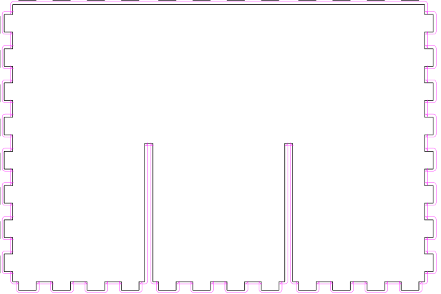
Here’s a screen shot of the same tray with the only change in boxes.py the burn. In inkscape I made it easier to see the stroke position difference by setting the widths to be the same, but the color to be different. The black is 0.1mm burn and the purple is 1mm burn. I approximately put them on top of each other so they’re not lined up precisely but you can clearly see that the purple part is bigger than the black one:
@markwal thanks for that analysis. I recreated your experience with and was able to zoom in and see the center line move. I guess its back to the experimenting with settings to see what i should be using then.
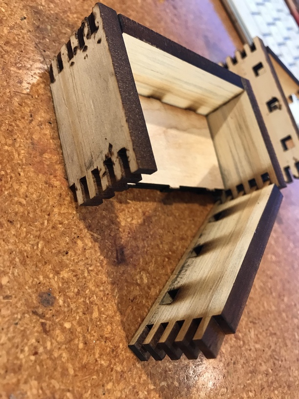
By the way. I also found that the tenons fit tighter into the holes than the box joints. I’m guessing this may be due to the material width direction being tighter since you wouldn’t notice as much the corners being slightly proud.
Perhaps it would help to experiment with increasing the material thickness variable by a little bit.
I wish there was a setting for making the pins longer. If anyone has found a setting for that, it would make a great difference in the amount of time spent sanding. I put a setting for it in the box generator I wrote, but I don’t have settings for dividers in mine yet.
Not a setting, but a potential “slow” work-around. I use Inkscape, but this should be easy enough to figure out in other software.
When I get the file of the tabbed box, I can show the nodes, draw a box to select all the nodes on the “ends” of the tabs/pins, and hold Alt and count out how many arrow key hits you want. Then I repeat that for the other sides of all the edges. That seems to work for me.