The OHP is WIP

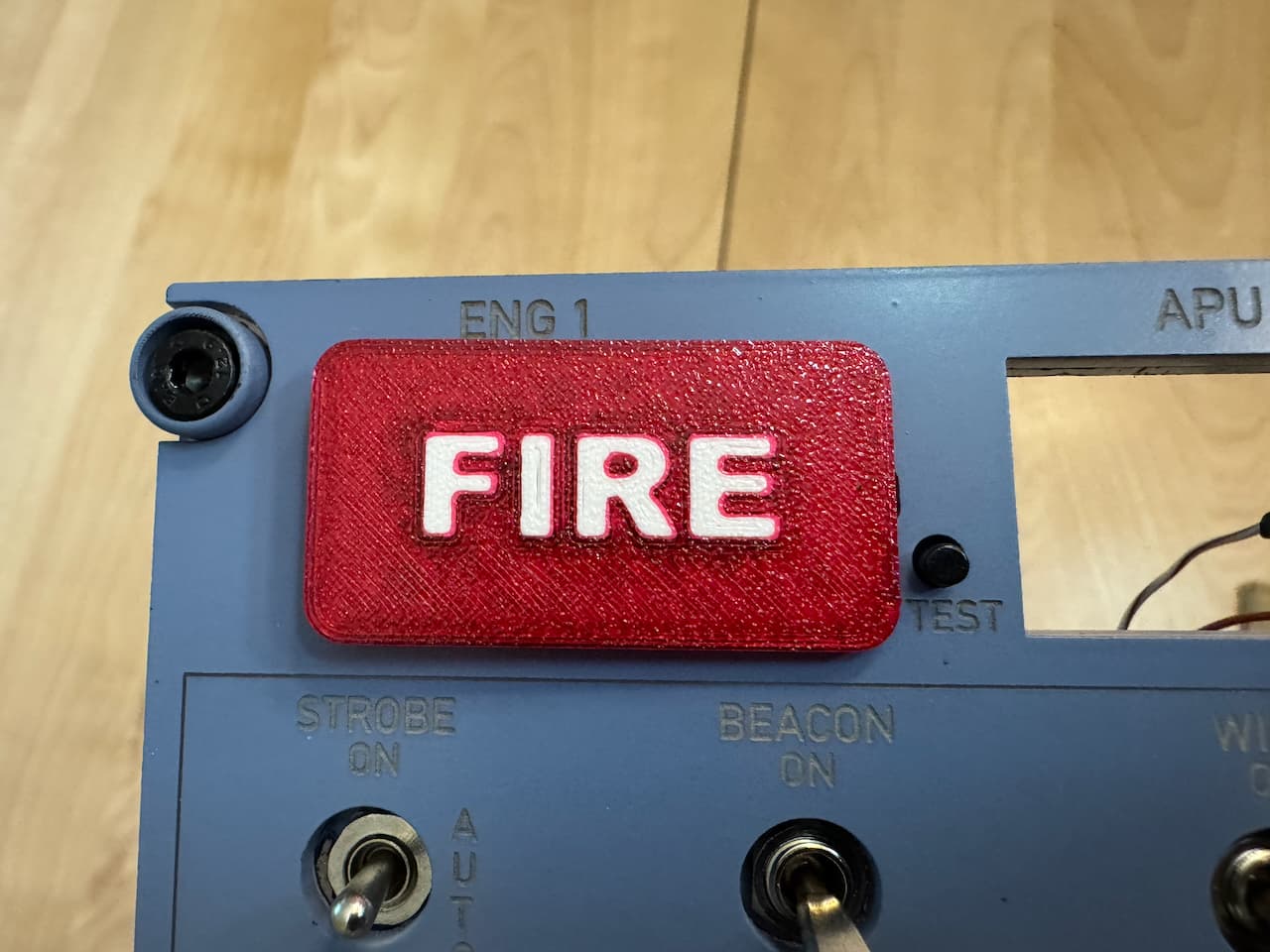
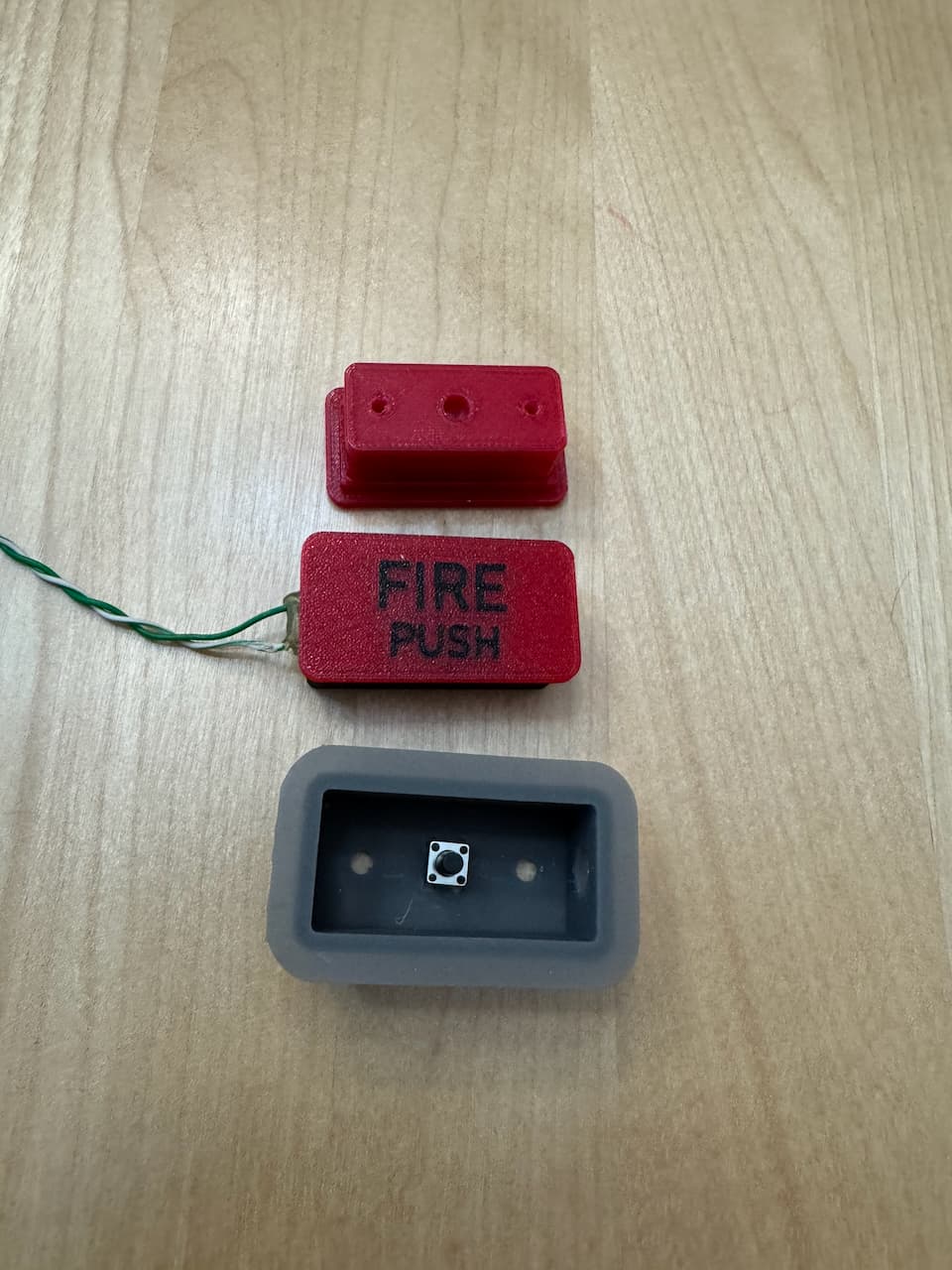
For those wondering what they are and what they do, MOSFET (acronym for metal-oxide-semiconductor field-effect transistor) and basically is a variable relay that can handle a lot of power (relatively). The problem with controls like board I am using is that it uses an Arduino Mega which while Mega as far as Arduinos go, it just basically a giant arduino with lots more of the same inputs and outputs. So if you want to power a lot of outputs such as LEDs (say the 5 LEDs inside each fire indicator) that well exceeds the output current limit of 40mA of each output, plus the classic arduinos run at 5VDC while the strips are 12VDC. So you need something that will switch 12V from 5V at high current (the strip in those indicators will draw about 500mA. You could of course use a relay, except relays need a lot of drive current themselves (not as much as they can switch which might be 10A for a little relay) but say 100mA for holding them energized. But a MOSFET will do the same thing with 1-2mA to control similar power outputs. So the MOSFETs I use are these:

HiLetgo 5pcs IRF520 MOSFET Driver Module MOSFET Button Drive for Arduino MCU ARM Raspberry PI

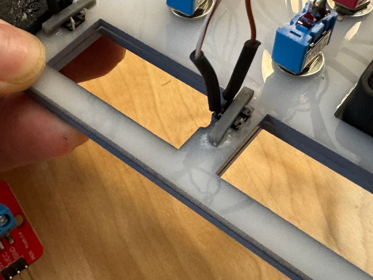
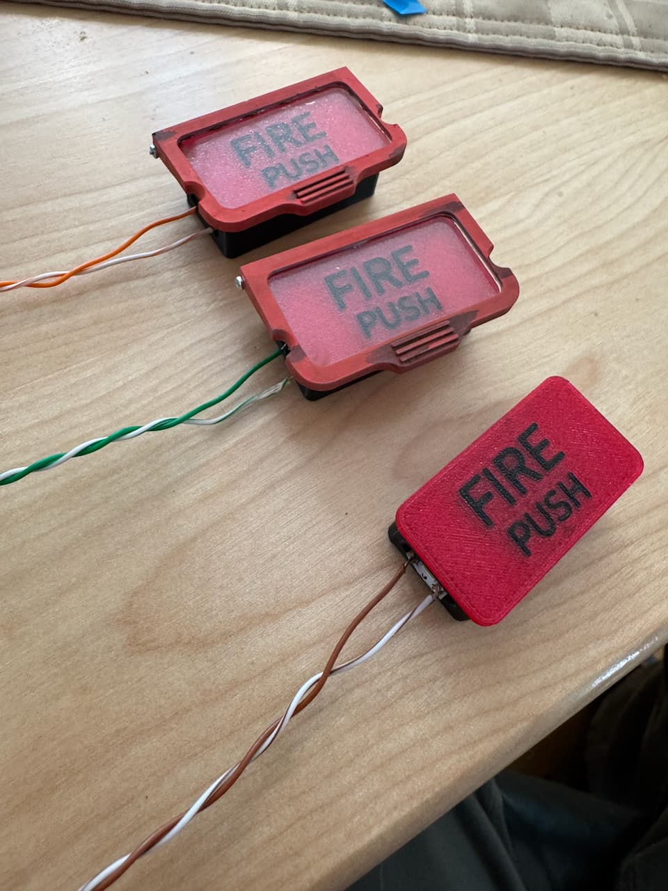
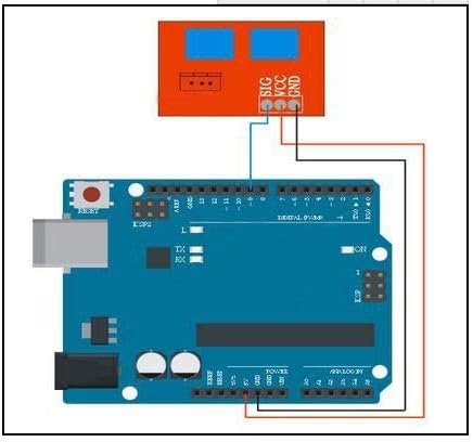
The black thing is the FET the little aluminum tab is a heatsink, and what you can’t see in that photo is in the blue terminals you have the high-voltage in (in my case 12V) and out. The control pin is on the bottom there labeled “sig”. Now the control side runs at 5V so I have to have both, in my case I am using a Buck-Buck 12VDC-5VDC converter so I know I have a common ground (a good way to blow a MOSFET is induce a current if you have different grounds!), so basically my 12V in splits to become 12V and 5V sharing a common negative. While the arduino will have to hold the MOSFET on via the sig pin for as long as the fire lights are on (I may do the backlight but not sure yet that would be cool to have it backlit only when the jet is powered up…) but haven’t gotten there yet. For reference those FETs can switch 0-12V at up to 5A. For those curious what that all looks like hooked up:

MOSFET mobiflight schematic

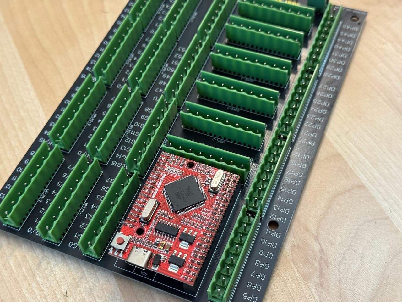
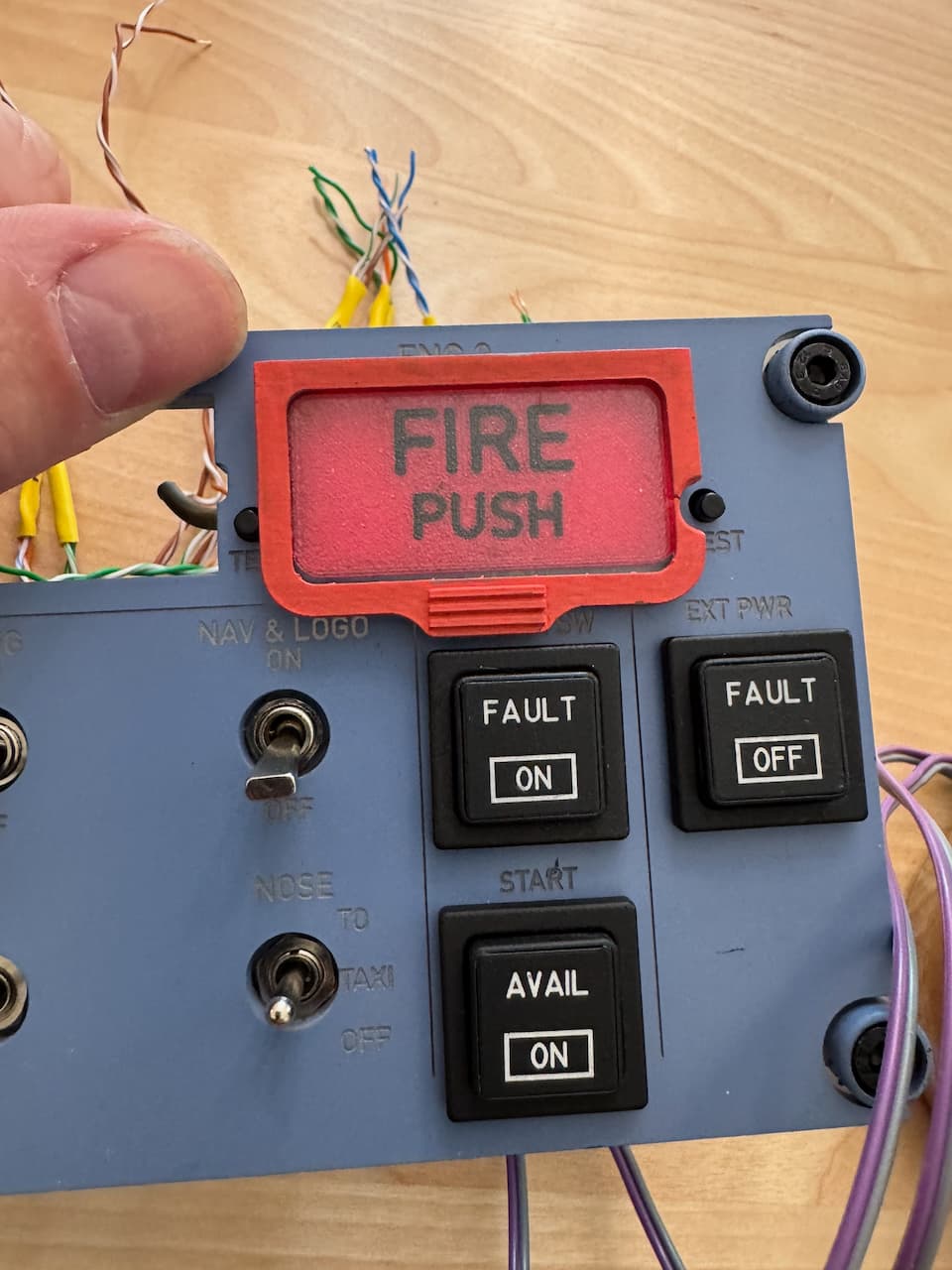
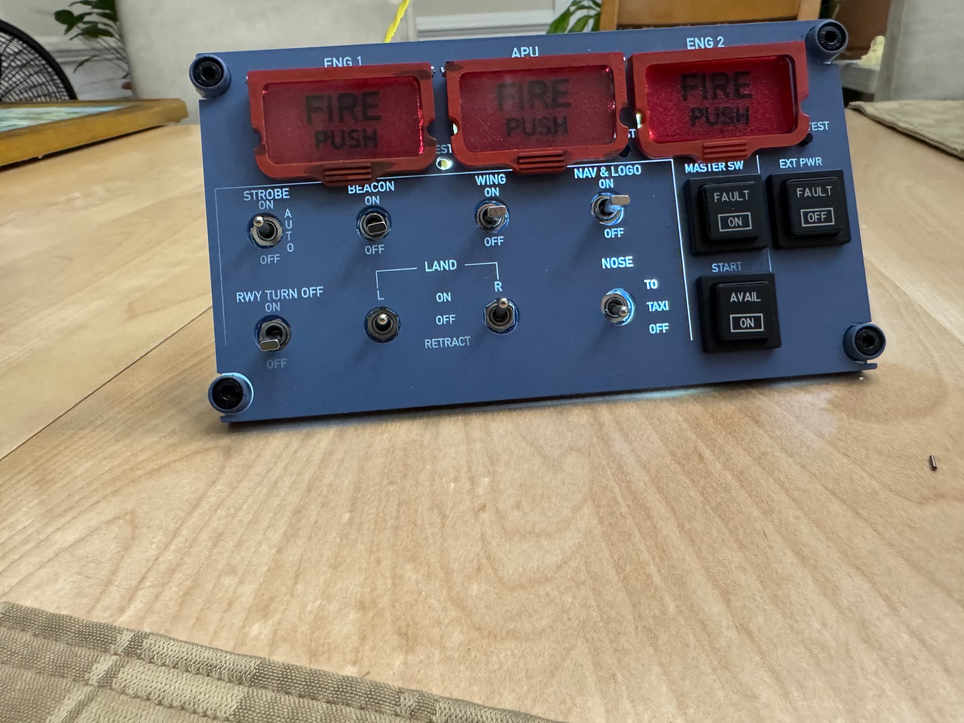
the final question is how you control all of this to communicate with the flight sim, well a wonderful group of enthusiasts built an open source package called Mobiflight (the portmanteau probably makes more sense in German) Any basically it is a giant switchboard that takes the inputs and outputs from the arduino mega to the APIs of the 3 majors sims (MSFS 2020/4, DCS and X-plane). It does more than just connect arduino GPIO though as it supports shift registers (need even more inputs and outputs than the 54 an arduino mega has? To paraphrase Bob the Builder, “YES WE DO!” so those let you sort of have a splitter on a given pin that you can tell hey turn on pin 7 bit 4, giving you many more pins effectively, although the shift registers are not as well protected as normal arduino outputs (which have all sorts of protection against idiots like me), A classic example would be a panel like this:

Media: 737SS MIP Annunciator Set

That would take a lot of output pins to drive it, but it all easily fits in a 16-bit shift register. (each colored pair of lines is a LED). The board I have has 4 of the 16-bit registers giving me an additional 64 pins effectively. Certain cockpits (like say a certain aircraft company which rhymes with Sewing, use a lot of 7-segment displays in their cockpit), which means since 7-segment LEDs are just 7 LEDs glued in a box to make the digits, so on the back you have 7+1 sets of pins with the 7 segments and a decimal point (hey, that sounds like an 8-bit shift register’s worth!!) You can quickly end up with rediculous boards with hundreds of bits. The only saving grace here, is the speed at which anything happens in a cockpit is glacially slow in the world of computers, even an arduino can easily keep up with hundreds of inputs and outputs.

Now one nightmare I am sure those of you who have done panels (of any type) is remembering what input you put the switch for , similar to where you left your reading glasses (and without a wife to remind you they’re on the table in the living room near the lamp, she can’t find her own but mine she knows the GPS coordiates of?) anyway, Mobiflight has your back. When you are in the windows side of this (the Mobiflight software only runs on windows) you kill the sim so there are no active I/O coming to the board, then you tell it to find an input say which may be a switch, rotary encoder or potentiometer and then you twiddle your input and voila it finds the one thing that changed (it has a confirmation after to make sure you selected the right one and some switch wasn’t somehow jiggling and false answered).

You may ask if the Mobiflight puts sufficient drain on the host PC to affect sim performance, well first off that sounds silly given how powerful a modern gaming PC is (to put it in perspective I have 16 cores, 128GB of DDR4 RAM, a NVIDIA RTX3090 all liquid cooled pulling close to 1000W when going full tilt in the sim driving a 4K monitor) so that machine is truly on the edge of its horsepower, but Mobiflight is less than 1% CPU and 128GB of RAM is way more than needed so it sits quietly on the side doing its thing. Now on really, really big sims they use 2 PCs a basic PC to run Mobiflight (and other auxiliary packages like SimBrief) and send all that over the network to the Sim machine, but I am nowhere close to that limit (I may be tempted to upgrade to a RTX5090 at some point and to that goal did upgrade my PSU to 1500W not long ago)

7 Likes

And today’s update is how I solved the tactile switch mounting. I had cut them out from the bottom layer and since I don’t have a circuit board behind the panel, I was somewhat stuck with how to hold them in. I made tiny little brackets on the Form3 in gray resin (they are about 1mm wide) that basically got CA glued down to the back of the bottom panel which snugs them very nicely against the front panel. You absolutely could laser them out of acrylic but I didn’t.

The buttons stick up just the perfect amount and have that nice clicky feel

Since these are hidden and the important surface is crisp and clean I didn’t even bother to sand the support points (because nobody will ever see this). CA glue is suboptimal but this will never get any real force

The other major progress today was soldering up the BOB (breakout board) which I used 737DIYSIM’s breakout board, and got the board soldered up so now I can punch down the wiring harnesses into the RJ-45 keystones and actually connect it to the sim! The arduino mega on there is some clone of the mega (which is fine for this purpose), the BOB is nice as it has all the power stuff on the front edge via jumpers (internal vs. external 5V, PWM or full strength for LEDs, 4 shift registers, and I love the whole screw terminals that plug in as a unit concept! As soon as my Prusa XL finishes the current 2 day job I will print the case for this thing (of course in Airbus Blue).

And just as I get all of this done, WinWing actually opened pre-orders for the new Airbus gear!!!

(I cannot wait for the panel with the gear lever, airbrakes, flaps and throttle). I already have all the panels to mount to ready to go for the pedastal… Their stuff is truly amazing (especially at that price!)

11 Likes

DIY vs. real, I was researching a subtle detail in the fire warning lights for the airbus and came across this company: simulatorcomponents.com

So let’s say you’re building a real™ simulator, at a certain level you are required to use actual aircraft components and instruments and you need a component. You could of course call up airbus or Boeing and buy such a component like the airlines do for spare parts, but those can be insanely expensive. Well that’s where companies like come in, they buy a decommissioned or wrecked aircraft and strip all the parts in the cockpit that can be used in a simulator, now to keep costs down you don’t get an airworthiness certificate so the part is issued for with a SSV). But that doesn’t make them any less insanely expensive for normal people like me. Here are 2 shocking examples:

Winwing a320 FCP+ 2 EFIS panels:

https://us.winwingsim.com/view/goods-details.html?id=925

tLDR: $350

Actual A320 ones (used):

https://www.simulatorcomponents.com/product/c12850ac03/

TLDR: $115,000,

plus you do not want to see the bajillion pin connectors on the back! The winwing has a single USB-C and a back cable that joins all 3.

This one truly blew my mind, in my panel I use multiple on-off-on mini-toggle switches (so called guitar switches) and they generally cost me $0.75 each, but this insanity is $1400 (for that price it should do a manicure each time you actuate it!)

https://www.simulatorcomponents.com/product/pn-100-230386-1-switch/

Oh and in case you look at the simulator components page, yeah their whole description is the OEM part number. But it is a fascinating look into how the “pros” build the components like the throttle gates which are backlit steel (a non obvious solution) actually do it the way I did with 2 layers (I assume acid etched or fiber laser engraved) on the outer sheet metal and then the inner has a diffusing layer and has holes punched in the inner layer for light bulbs. The Kory buttons (the push buttons with words on them that have color LEDs underneath) are about $1000, compared to the $50 I bought, theirs have a 50-pin connector (because these all use actual lightbulbs, not LEDS) so you can’t have one lightbulb, so they have like 25 and for reasons don’t seem to use a common ground plane so each bulb is 50, then connectors for the actual switch, meanwhile mine use 4 pins for switch and 2 LEDs, fiber laser engraved words and colored lenses of laser cut acrylic all on a custom PCB with the LEDs surface mounted

8 Likes

That came out great! I made new panels for a neighbor’s Cessna 340A. He was refurbishing his panels so I made new ones for him using 2-tone Rowmark Acrylic. I definitely measured 3x and cut ONCE! LOL

Now, just to get around to doing ours! Word got out so I have a few more different airplane types to work up.

7 Likes

after looking at a real one realized the text is black so switched the PETG to black and tried to virtually unreadable, finally figured out white works when it’s deep but black needs to be shallow so now the text is only 0.8mm of a 2.5mm deep panel and raised the infill to 40% hex. You can see the 2 different depths of black compared. Next onto the guard cover (that will be partly done on the GF)

Bottom was the shallower depth black

9 Likes

Just did the first switch guard on the GF (that’s 1/16” [1.5mm] clear acrylic) and a SLA printed frame (painted with RAL 3020 Red Acrylic). The hinge is a simple M1 screw into a medium PG acrylic block with a hole in it. (I don’t have the patience to engineer a sprung hinge like Airbus did)

haha, but don’t think I designed that cutout for the test button on the first try… Sure I am an idiot but at least a teachable idiot! :grinning_face_with_smiling_eyes:

10 Likes

Sigh, I spoke too soon, a partially trainable idiot… Oooooh, there is a button on BOTH SIDES of the indicator that need cutouts… Well a quick draft print (hence the little dents) and we have clearance for the both test buttons (trust me they are lined up the panel is just tilted relative to the camera):

And then I did the first test hinge. Wow, I was not quite aware of just how small the hinge screws/nuts were when I specified them in the CAD model (sorry no bannana as not sure how that would be a valid size here - my fingers are not abnormally sized):

13 Likes

Got the first hinge done (man those screws are tiny in my hands), My son noted they needed to be grunged up as the ones in his plane have a fine coating of burger grease and coffee, so a little burnt umber oil paint and Tamiya Panel Liner and we have greasy grunge (somewhat interesting [not really] is how the panel liner flowed to form those weird almost stripes except where the grips are, it moves by capillary action). I am going to sand the back edge a bit more and repaint since that looks rougher in the photo than in real life but doesn’t feel that bad…:

8 Likes

Being an IT guy and developer, I always worry about maintainability and honestly the fiddly parts to make the button go together was just not going to last (plus since it was many parts getting the tactile switch underneath to work was very unreliable). But with CAD and a 3D printer with 5 heads, easy problem to solve, now the black case (to prevent light bleed) is simply part of the button, and to make the lighting built in, it now has a groove in the middle that lets me put the LED strip (it is around 10 LEDs inside) so voila! little bits to glue on, takes 2 extra grams of filament (love the way the XL does color swaps! No Bambu poop chute!). The Red is transparent PETG and the black is jet-black PETG.

Anyway, this is what they look like (there is a groove to mount the guard hinge plate now)

In case you are wondering why I am spending so much time on the fire indicators, it’s because on this panel, they are the only switch/lights that aren’t simply off the shelf (the toggle switches are just toggle switches, the Kory buttons are Kory buttons, so these had to get made)

10 Likes

Redid the panel in the glowforge as the spacing did’t work. Just noticed 2 of the buttons popped out for the pic (this was a test fit before gluing everything in). Just a flashlight behind

9 Likes

Today’s exciting revision was I was looking at the fire indicators and while my original plan was just to have them light up and not make them buttons as well (just press the virtual button on screen during the actual fire) I suddenly realized how I could alter them to be pressable buttons. So the design is pretty simple without major rework of the panel, I SLA printed a back, that has a mounting hole for the tactile switch (in a 6x4 layout) and then the two holes on the sides are because since this originally was just getting glued onto the panel there was no provision for keeping it from popping through, so that holds a pair of M3 screws with light springs over each to provide a robust spring back (the button is sprung but just relying on that left is rocking and binding).The flange on the backing sandwiches between the 2 layers of acrylic that make up the panel (the flange is 0.75mm thick) The holes on the sides let the wire for the LED strip to come out. I also got stranded twisted pair wire instead of cutting up ethernet cable (the idea is these all punch down to a RJ-45 keystone) so redoing all the leads is on deck for the day.

11 Likes