To adjust for kerf or not to

One reason this is a big issue is that with most CNC machines you have a separate CAM program that does the kerf offset and produces gcode of the adjusted toolpath that goes to the machine. That means you can use what ever CAM program you want. Glowforge with its cloud approach has taken over the CAM stage and doesn’t accept a gcode tool path. So it needs to be able to do everything you can do with other CAM tools or it makes the machine less capable / flexible than a conventional laser cutter. Either that or it should accept a gcode toolpath.

4 Likes

Hold on there. Glowforge accepts SVG. Are there CAM tools that accept DXF or SVG and can output same? (All those fancy toolpath simulations have to come in some format.) If not, coding one up should be a fairly simple matter – SVG is complicated, but the parts of it that GF is going to use really aren’t. Or a gcode-to-SVG filter (once again, for the parts that are meaningful for a laser cutter). The longest part of the programming would be finding the right winding code to steal.

Oh, wait. Inkscape is scriptable. So are we talking about anything more than code to figure out which loops are exterior and which are interior and doing kerf/2 outsets and insets before saving as lase.svg?

1 Like

Most CAM tools output gcode to send to CNC machines. They don’t output the tool path in any other format because it has feed speed, etc, added to it.

Yes I can write my own tool offset code, I did so when I made my first milling machine / 3D printer, but why should I when I spent thousands of $ on a Glowforge from a site that boasts it as one of its 12 revolutionary superpowers?

1 Like

How did I miss Kerfgate yesterday? Here I am thinking nobody is posting anything good to read. I kept skipping over this thread thinking it would be boring… How wrong was I? Thanks for all the entertainment, and yes between it all some really good information about kerfs.

16 Likes

LOL

2 Likes

Oddly enough, there is (at least) one CAM package that will not only output an SVG, it’s apparently specifically.intended to be used with a Glowforge. Here’s the first post that I know of that talks about it…

And here’s a thread that @Clone started to talk about it further…

I’ve tried it in both Fusion 360 and HSMWorks and it works pretty well. It’s not perfect, but it’s OK. @Jules. I know you’re working on a tutorial to show how to offset sketches in Fusion 360 by a parametric value, maybe I could supplement that by recording a video about how to use the Glowforge post processor in HSMWorks (or maybe even in Fusion 360, though that video has already been made once).

Why do I say it’s just “OK”? Well, the SVG it generates is less a collection of shapes and more a collection of lines. Each line segment is its own entity. The laser cutter that I happen to have doesn’t seem to have a problem cutting with a mishmash of hundreds of individual line segments. This laser, perhaps by virtue of using a printer driver (a form of CAM, to keep the nomenclature consistent with the rest of this thread), seems to automatically join the lines together.

So, what’s the problem? Unlike my printer-CAMed laser cutter, Glowforge has had issues with unjoined mishmashes of lines. Here’s a post from @dan stating this…

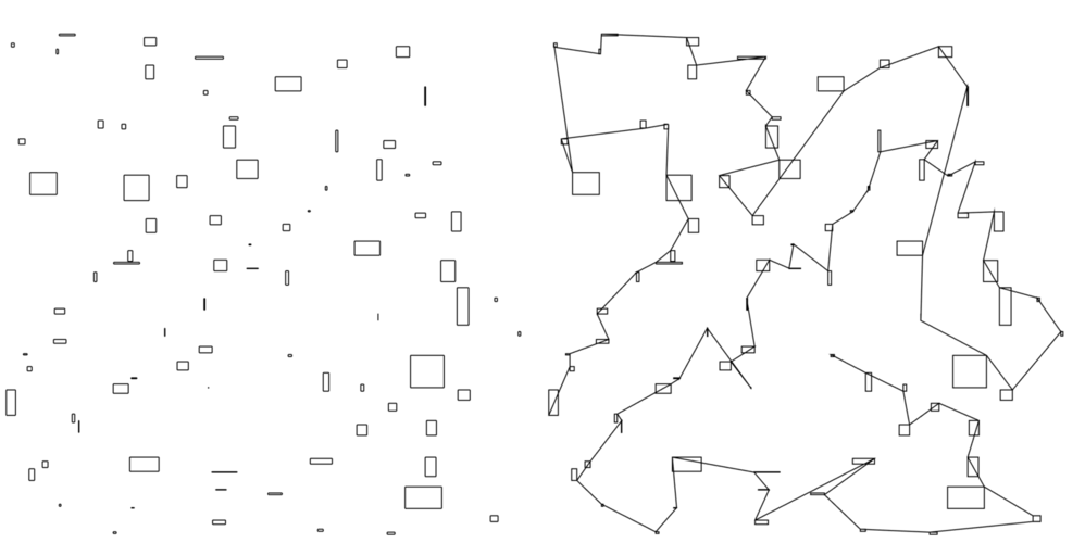
OK, fine, the lines aren’t joined. No big deal, right? Sorry, that is a big deal. As best as I can tell, joining the lines in Inkscape means selecting two joined lines individually, then selecting the point at which they are joined, and then executing the “join” command. A process that would literally take hours with some designs. Illustrator is a little better, at least you can select all the unjoined lines at once, but it has a strange proclivity of also ADDING a bunch of unwanted lines in the process. Here’s a “before and after” image I created and posted in the above thread to illustrate the mess this creates…
https://community.glowforge.com/uploads/short-url/zUHGpvI63KTRsI0WIPrtFuZUCAN.png
This is better than Inkscape, but not by much. I don’t have Corral Draw (or even know that it’s actually “CorelDraw” :stuck_out_tongue: ), so I haven’t tried joining the lines created by the Glowforge post processor in that yet.

Rhino will join these lines perfectly. OK, cool, so it must be that I just like complaining, right? Although that might be the case, Rhino has one fatal flaw in this regard: it doesn’t open or save SVGs. At least, the version I have (v4) doesn’t, I can say that for sure. It’s possible it’s been added to the newest version (v5) but my quick internet searches seem to suggest that opening this format is still missing from Rhino’s amazing file-compatibility list.

OK, so can’t I just open the SVG in Inkscape, save it as a DXF (I’m assuming Inkscape will do this), then open the DXF in Rhino, join the lines, save the DXF, then open the DXF in the Glowforge software? I think that will be possible BUT, here’s a somewhat recent post from @dan on that subject…

SO, currently the workflow would be HSMWorks post processor → SVG → Inkscape → DXF → Rhino → DXF → Inkscape → SVG → Glowforge.

Is that the END OF THE WORLD? No. It’s fine. It’s just a bit of a drag to have to jump through SO MANY HOOPS just to WORK AROUND a deficiency that was a feature promised from the beginning…
https://community.glowforge.com/uploads/short-url/grvYjZyyXs0SuoJqoFLBbOyAhhH.png

Call me crazy, but I’m not the biggest fan of being promised things and then find out that those promises have strings attached (it currently sounds like you have to buy Proofgrade material to have the promise fulfilled).

And yes, I know the workflow can also be Fusion 360 → parametrically offset sketch → DXF → Inkscape → SVG → Glowforge. As I mentioned earlier (post 43) this workflow (while completely possible) is riddled with issues when dealing with parts and assemblies that are more complicated than a few 2D extruded sketches.

My current workflow for my primitive laser is SolidWorks → DXF → Rhino → offset → Trotec thing.

10 Likes

Im a bit late to the party here, but I would have to say manual kerf adjustment would be INCREDIBLY helpful. I cant stress this enough.

There are many times where I am cutting multiple pieces out of different materials that will have different kerfs, and I really dont want to have to go back, re-edit the file for a different material, re-export it, and then cut. That would be a pretty big pain in my butt. Sometimes I have to work with very precise clearances, and having one piece stick out more than the rest would mean a lot of additional work or re-work.

A simple example that I can show here would be the phone stand on the front page of the glowforge site:

Simple design, but 3 different materials. I wouldnt (who would?) want to have to sand the whole thing down afterwards because I couldnt adjust the kerf on the fly. I also wouldnt want to go back and re-export that file 3 times with different kerfs, much less try to design around a mechanical device that would use multiple materials. I currently have to do this with my chinese laser and it SUUUUCKS.

As someone who does a lot of multi-material work, its something that would go high on my list of features to have. I think it would be pretty easy to implement as well. (see below)


17 Likes

Another point that popped in my mind:

I also use a lot of materials that glowforge will more than likely NEVER sell. Therefore I will be out of luck if Im not using a proofgrade analogue. Not to mention I either have tons of scrap or can run to the hardware or exotic woods store on a moments notice and get what I need instead of ordering something online and having to wait. While Im sure proofgrade will be cool, I cant see myself using it more than whats available locally. The formulations for most of these materials arent going to be any different.

Not only that, but even with certain materials I might want to change the kerf for the last piece. For example: EVA foam. When hit by heat it contracts. If I was building a multi-layer object out of EVA foam, I might want the top and bottom pieces to be hit with a heat gun to seal up the cells before coating it with plastidip. This will cause them to shrink and be a different size than the rest of the pieces. If I can manually adjust the kerf for these two pieces, or have a setting called ‘heatgun shrunk EVA’ ive saved in the menu, I can just select that and be on my way for the top and bottom pieces. No more bouncing between software EVERY TIME I have to cut multi-layer EVA.

A manual kerf just makes sense.

11 Likes

Good points. One humble suggestion – add a “Sample” or “Suggestion” watermark across your UI image. Sooner or later, it will get cross-posted as “look at this new feature!” I’m guessing sooner. :innocent:

4 Likes

I liked to think about it as “Kerf Wars”

As long as everyone goes home safe…

7 Likes

Agreed, all that those of us on the CNC-persuasion side are asking is that we be given the choice of selecting a kerf allowance and whether or not to use that option. We (or at least I) have no wish to force them to use a kerf allowance if they don’t want to. Come to think of it, make the default kerf allowance value “0.000” (inches or mm) and we can all be satisfied and GF only needs to add one input box to the UI.

4 Likes

Excellent point. If you want to sell the advantges of a cloud approach, you’d better have all the features that users want, especially if they are commonly available elsewhere.

3 Likes

Can you all who are interested in discussing the should or should nots on what SHOULD the Glowforge have in regards to options available currently with your CNC CAM stuff please create a new topic so its easier for those folks interested to find?
This post was originally created to explain what kerf is not how to do it. Thanks😀

6 Likes

Im all kerfed out anyways lol

3 Likes

I was so close posting similar pictures yesterday but decided I’d just keep my mouth shut :innocent:

Okay - been busy tutting (and losing this thread for some reason) but the problem with disconnected lines has nothing to do with the program that is receiving it, and everything to do with the program that exported the DXF.

That’s a problem that I’m very familiar with from the cutter world (and I’m sorry to have to keep referencing it, but we saw it there all the time.)

The bad news is - it might be how Solidworks or the HSM Processor, (whatever that is), is exporting the DXF file. (I’ve tested Rhino, and it exports connected paths. Similar for Fusion 360, Illustrator and Inkscape.)

My bet would be on the HSM thing…Solidworks is in too wide a use to do something like that unless it has to do with toolpath assignment.

If you can export your sketch as DXF directly from Solidworks - you can then, if necessary, convert it to SVG in Illustrator or Inkscape.

If you load up a DXF direct from Solidworks - i can test that in Illustrator to see if the paths come across as joined for you.

That workflow - jumping between that many programs, isn’t going to be necessary.

Mine is Fusion 360 export DXF> Illustrator (or Inkscape) convert to SVG > Glowforge cut

I’ll bet you can do that too.

3 Likes

I have imported .dfx files into Corel and sometimes they are connected but more times than not, they are all broken into segments. Easy fix with join nodes -non close curve which will close the shape by drawing an extra line between the first node and the last. Then export as .svg.

Otherwise and almost always…I design in Corel so its one conversion to .svg and then the Glowforge

6 Likes

Anything that gets created in the AutoDesk123 Make program gets exported as discrete segments in the DXF.

It’s annoying as hell - I have to circle everything and Join, circle and Join…so yeah, it can be a problem if you are trying to do something that is spaced too close together.

One of the reasons that I listed all of the programs that I used in the Shared Free files that I posted was so that if Tony and crew needed to know which programs were causing problems with unconnected segments, they would be able to pinpoint the problem. (And I’m not sure if I bothered to join everything in all of those…probably left a few unjoined so they could test with it.)

That one is nice for aligning tabs and slots, but almost not worth the trouble of cleaning up the results for cutting.

3 Likes

I have a feeling that a lot of my work will end up being run through Vcarve Pro as it will allow me to optimize vectors making sure they are closed and control start stop points.

3 Likes

The DXFs exported from SolidWorks aren’t joined either. I agree that the state of the exported file cannot possibly be attributed to the program opening the file.

I wasn’t speculating about the workflows, I was describing the only way to get from SolidWorks to SVG using the software I have and the following constraints…

  1. I’m not willing to enter “fake dimensions” into my designs to adjust for kerf
  2. I’m not willing to be driven mad by watching my cloud-optimized laser cutter bounce around the bed randomly
  3. I’m not willing to select all the lines I want to join individually and I’m also not willing to clean up the mess left by joining lines in Illustrator. I didn’t know how CorelDraw handles that operation, but it sounds like it mimics Illustrator (in other words, it sounds like it’s garbage).
  4. I’m not willing to clutter my SolidWorks parts or assemblies with additional sketches that serve no purpose other than to adjust for kerf