Traveling salesman problem revisited

Wait, don’t close the door, I’m sure I could interest you in a set of *SLAM!*

Apologies, but this post is going to be complex, text-heavy and kinda nerdy. You have been warned.

So I finally got to the traveling salesman problem. This is a topic that has been covered a few times before, but I had some ideas about how to do it a little differently, and now with clean corners, it seemed like it was about time.

The traveling salesman problem is a broad topic, if you have no idea what I am talking about I suggest you go read wiki on the matter. I’ll wait.

OK now that we’re all up to speed here’s what I did: I decided the thing to try was to vary the line width based on length of the line segment. To wit, I wrote a php script that does just that: color codes and thickens lines based on their overall length.

So, to start, you need to be pretty technically adventurous to try this. It’s not hard, but unless you’re a software developer/system administrator it is probably unfamiliar territory for you. The process I followed was from this page:

And after you read this thoroughly you might think “Dave, that script already varies the line width!” Yes, it does, but the way it does it is by making filler polygons and circles, not true line segments, and was completely against my plan here. I wanted to be able to make this entirely by scoring, with no engrave, filled polygons wasn’t going to do it.

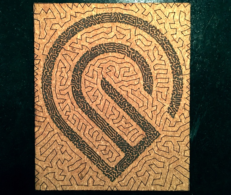
What’s this get me? Well if I can isolate the lines by length and group them into different colors, then i can treat them differently in the GFUI, specificially by changing the focus height, which will make their line weights on the final piece be thicker or narrower. I was pretty pleased by that little idea. Here’s what it gets you:

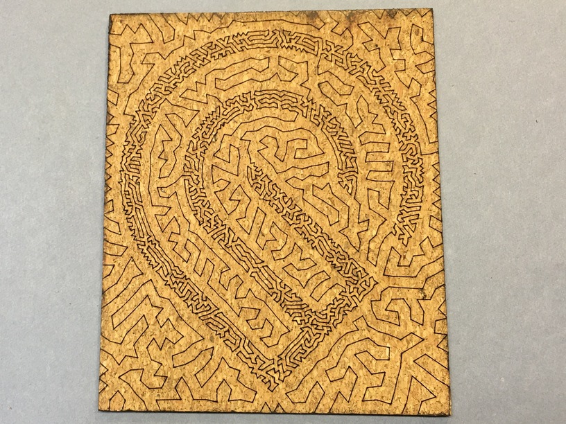
I chose cork because it scores/engraves jet black with very little power, I could go as fast as I wanted. Here it is with different focus heights to make thicker/thinner lines. This next picture is a score, a single line path, there is no engraving here.

Compare that to the first picture, where the paths were unified and scored at a nice thin focus – the lines are all thing and the same thickness. It’s still pretty cool, but I wanted the density to change:

I applied the same technique on a black and white illustration of a black labrador retriever – again this is a pure score, no engraving (10.5" x 8.75", 50 minutes at 400 speed):

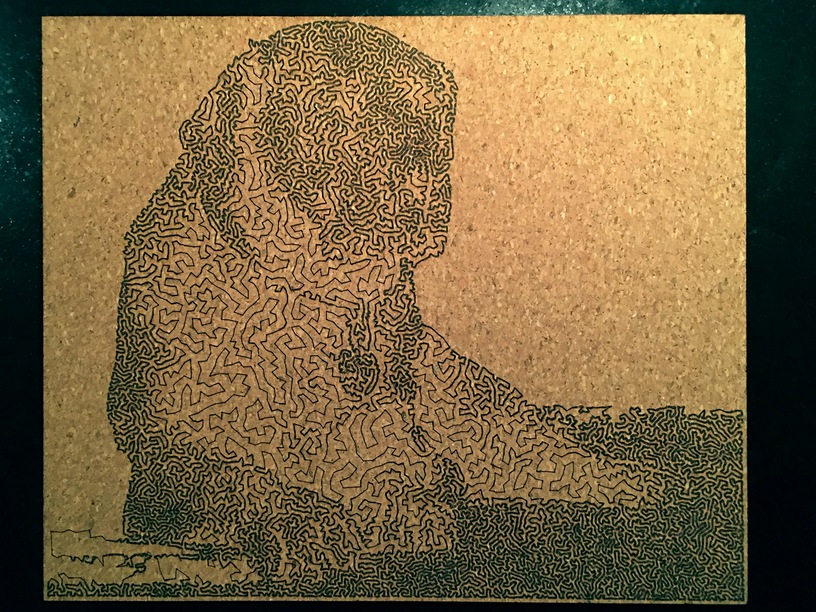
As a proof of concept it does work on photos, but personally I think the results are best on extreme contrast graphic images, like our vaunted GF logo. Granted, this is a sample size of two, but still.

I’m feeling givey tonight, so if you want to play with this, have at it:

gfoutput

(Right-click here to download the SVG)

I am also feeling extra givey tonight, so here’s the php script that will do the color coding and line weighting. To use it, grab the svg that is produced by that earlier link, break apart the path so that every line segment is a separate ungrouped path object, and then apply the php script to it.

tspchomper.zip (2.3 KB)

Disclaimer: I am by no means an SVG modifying expert. This only works for a very specific svg treatment, you have to follow the steps as written or I can’t really say what you’ll end up with. SVG’ers beware. The code is fairly well commented, but I’m not supporting this code or php installation, you guys are on your own. If you’re stuck, the internet has a metric ton of resources for how to do all that stuff, google your face off.

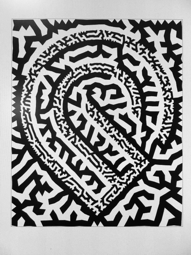
And as a super funsies project, the paths make a continuous loop, so I joined all the various nodes and set it to a fill. This would make a crazy engrave/inlay… and now that you have the file, I say you should totally do it.

So, why? Why do this? Other than aesthetics (which are subjectively kind of cool), it’s all about trying to make “engraves” that are faster than the traditional method. For example: the GF logo single line weight TSP score at 4" x 4.75" at 400 speed took almost exactly 6 minutes. Not bad.

PS also, not for nothin, but that filled file is pretty much 99.9% of the way to being a labyrinth. @jbmanning5, surely we can monetize this?

37 Likes

Now if you could just programmatically assign the speed, power and focal height. :slight_smile:

7 Likes

Yeah it was kind of painful to go through and set those manually. I used a single stored setting to set the power and speed, but then manually changed the height on all 16 different colors in the Labrador retriever. The GFUI is just not optimal for this.

2 Likes

I am going to do this, but it is totally over my head, and even if I do it I won’t really comprehend what I have done. It is ok, though, because sometimes you just have to trust that doing something is worth doing.

6 Likes

I believe in you! It’s really not that hard, you just have to follow the directions. In the end all the hard work is done by the programs, and it’s just a matter of sticking to the plan.

1 Like

Very cool project, thanks for the details!

1 Like

I am surrounded by geeks, nerds and dweebs. I fully expect a game of D&D to break out in some backroom thread any time.

And yes, I’m not complaining, I’m very impressed.

10 Likes

I only have experience with the GFUI and the Universal Control Panel, and the UCP isn’t any better for it, IMO. Probably less so. Unless I don’t know how to use it very well, which is entirely possible.

3 Likes

Oh, how fun!

1 Like

Very cool. I’ve said before the GF had a standard set of colour to settings this sort of thing would be much easier (as would circulating designs in general).

THough maybe in this case that is an unreasonable request, because you need 20 versions of a score I suppose.

It is possible to embed meta data into SVG files - wouldn’t it be cool if you could do that for GF??

Really like what you are doing there, I have two settings score and wide score, but never as many as you must have had for this.

I think there is a huge opportunity for more computer assisted artwork and a laser.

3 Likes

Wow, very impressive!

2 Likes

I just realized that the same principle could be done with the voronoi result, instead of length of path, I can apply the same concepts to the circles according to their radii.

I’ll probably update the php to handle that. (He says, not at all sure what that looks like.)

Ages ago I did a proof of concept with a custom halftone using tiled clones. I could apply the line weight concept there too and would probably get interesting results. Aha here we go:

I wonder if tiled clones combined with turning on scaling line weight would let you get even closer to the desired end result. Hmm.

4 Likes

With my Lasersaur system, you could leave text in the SVG and it would read the settings from that. The text was something along the lines of specifying the RGB value of a line, then the power, speed, and focus to assign.

It was REALLY nice to have that available, as I could bake the settings in to a file and know that if I return to it years later I just make minor adjustments for variations in material (I would name the files themselves to include type and thickness of material)

3 Likes

Interesting, and not a bad idea.

Even if GF wanted to keep the “colors” method, it would in theory be fairly easy to work out a color to settings mapping a bit like our current saved settings UI. It would require that you know and preset your colors and whatnot, so your text option is a whole lot more intuitive.

My take on settings being embedded in the file was always a bit of “eh”, because it seemed like it wasn’t any easier than doing it in the UI. The text method you describe is a great deal more user friendly than all that, so I’m into it.

1 Like

very nerdy and very cool

1 Like

I think it could be done maybe a few ways and done in such a way that it would be an advanced user thing.

Maybe something as easy as naming elements in the design software, and if those element names match saved settings, it applies the saved settings.

Or you could have a script that searches the SVG file and does some kind of find/replace with the color code and inserts S=, P=, etc.

They DO have a way a doing it, I’m pretty sure, since the PG designs can utilize the score function automatically. I’m pretty sure they are using a custom namespace in the SVG for that.

3 Likes

This describes the system in Lasersaur. I forgot they didn’t have a variable focus height in the build, so it wasn’t included in the LaserTags system. But they also let you specify the order of operations for the various cuts.

A system like this would be fantastic on Glowforge, since text isn’t processed as an engraveable element anyway. For simple jobs with one or two settings to dial in, this is pointless. But for things like material test grids, where you have 100+ different settings to program, this would be a godsend.

6 Likes

Trust you to come up with this!!! I think you misspent your youth not as a genius… :grin:
Seriously, This is on another level of thinking!

3 Likes

Eesh, you are doing it wrong if you need 100 :wink:

1 Like

So I did separate out the circles by radius, I haven’t thrown it in the laser to see what can be done with it. Someone else want to do it?

voronoitest

(Download link if you want)

4 Likes