That’s great! I can spell-unless the autocorrect interferes- but I can’t do math anymore. I made it through calculus in HS, but that was more than 40 years ago. I wish I could get gold  !
!
3 Likes
I FINALLY got around to printing this…and used it for the first time and the accuracy was SPOT on! So nice especially in the corners where things are skewed! Thank you @MyDogsThinkImCrazy for all your explanations! I used the legos:-)
5 Likes
I am glad you got to try it! It is really accurate. I have always loved it.
2 Likes
I really want to try this but haven’t yet! I know I’m going to have questions… lol
3 Likes
Lol well jot down them as you get them and I’m happy to help. But just try it and see for your self.
3 Likes
Hi there!
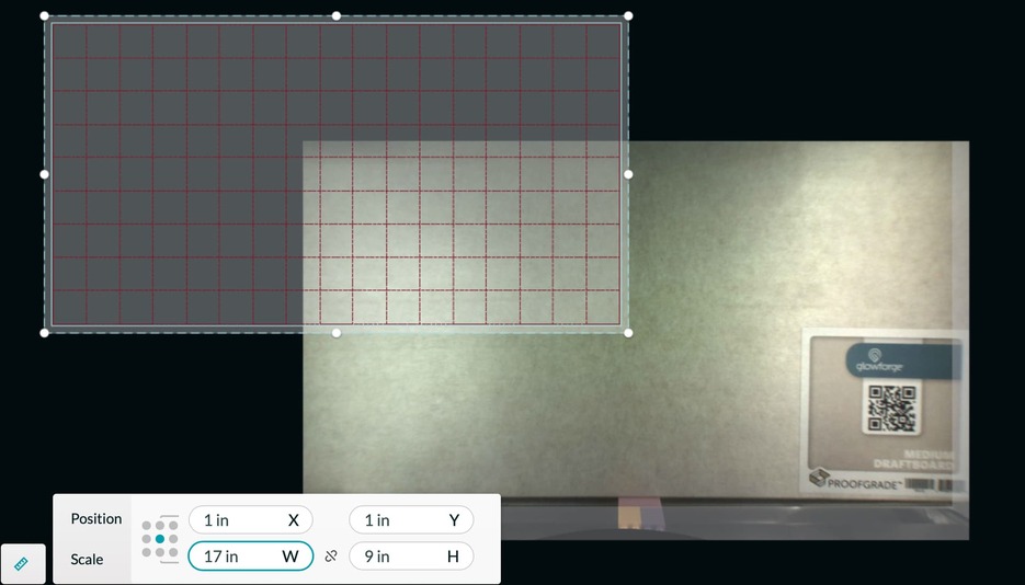
Very (very!) new to this, I’m trying to follow your instructions, but when I set the x, y coordinates to 1" it ends up over here like in the pic… Am I doing something completely wrong, or just going mad ![]()
Would appreciate any help
3 Likes
It looks like you are orienting the center of your design to the position indicated. The blue dot in the position grid is what is being placed at your indicated position. If you move the blue dot to the upper left, your grid will orient the upper left to the desired position.
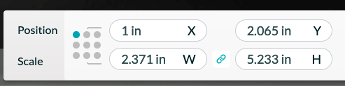
7 Likes
Yup! Like @dklgood said. To make the grid you want to have the grid start where the top left corner is at (1,1). With the glowforge app the default for item is the center. When I use the grid I often use the center points.
3 Likes
thank you so much! that makes so much sense now! 
2 Likes
Reading the instructions and I have a couple of questions - You said V2 was for when the crumb tray is out and for engraving only. Does the height of the grid change the alignment (meaning if I put it on top of the crumb try will it still be accurate)? (If not, can you point me at v1 file also?)
I can’t help but wonder if a L shaped version of this grid for on top of the crumb tray that you could use to line up other materials against would be beneficial when you want to cut something out and still need alignment accuracy. (Think about embroidery tools for pocket placement on shirts as a example.) Thanks!
1 Like
So here is the link for V1:
https://community.glowforge.com/t/reinsertable-grid-file-and-tutorial/93366
The V1 is for crumb tray in or out but you use to front door to line up. V1 is still a fine option but I have a pro and a plus and they are very different in their front doors so I designed V2 to be independent of the front door. V2 also focuses more on use on the Z axis. I go over in the examples on V2 but also in V1. The coordinates are not effected no matter where on the z axis (so you can raise and lower the grid and the points stay).
I have another tutorial that goes over how you can put a grid on the bed on the glowforge.
The reason why I say they are not for cutting is because you should use the crumb tray to cut. There really is no reason not to cut on the crumb tray because the max thicknesses for cutting is .5” and that is the allowed thickness to be on the crumb tray. I am sure you can use the grid for cutting but you would be destroying the grid each time if you are cutting on it and it would waist more material. Doing more of an embroidery holder design is fine as well but the crumb tray has some variation on where you set it in every time and so it would easily get shifted and no longer be accurate.
I recommend this method if you want to use coordinates when cutting:
5 Likes
Thanks for sharing this, I was able to use some scrap pcs of wood to make my locators and it worked great (not as fancy as 3D printed). I still have a question related to manual focus and manual material thickness entry when not using the honeycomb tray. My basic question is how does the machine know where the “top” surface of the material is when you are using random risers with non proof materials? When you use a manual focus value, is that always in reference to a certain height in the machine (maybe the top of the honeycomb tray?), that is still confusing for me as I try to better understand the relationship between the material thickness, the manual focus numbers that I should be using to account for the material being set on different height risers. Sorry if this has already been covered in another post.
1 Like
Welcome to the forum.
Use the set focus tool and make sure that the red beam lands squarely on the material to engrave. It is not necessary to enter a material thickness or do any math. The Glowforge can only focus in a 1/2" range. The material to be engraved or cut must be between 1.5" and 2" off the floor of the machine. Have you cut the No Math Focus Ruler? It is very helpful.
2 Likes
Thanks @dklgood, I have been using the “set focus” feature for most of my first projects and tests, I mostly wanted to understand better following up on previous posts related to manual focus to adjust the focus point for efficiency or even certain effects, so that triggered the question in my mind if my material was within a certain height range within the 0.5" range but the machine doesn’t really know exactly where, how would a manual focus/material thickness adjustment would look?
Related to the no math focus ruler, is that the one with a bunch of Glowforge logos on it? Maybe I am thinking of something else?
1 Like
This is the tool to help you quickly determine whether or not your material is within the focus range with the honeycomb tray removed. No-Math Focus Ruler
It would be very helpful if the interface provided the focus height when the set focus tool is used, and this has been requested by other users. It would make it easier to do defocused engraves and scores. Until that happens, however, you can always do your own math if you measure precisely the distance the top of your honeycomb tray is from the bottom of the Glowforge. We used to have to do all sorts of computations before the set focus tool came along. Use the search function to follow many old threads regarding engraving without the honeycomb tray.
2 Likes
Thanks for your sharing your knowledge and for your patience, I have found so much good information on the forums help me get started, I can’t imagine the earlier days with no set focus. I do agree, having some of that information available would be so helpful. I have a friend that owns an epilog laser machine and he was so confused by the GF, I believe that he actually has a touch point of some sort to get the dimension and he can adjust his head up and down to adjust for different materials.
1 Like
I have not been ignoring your questions. I am hoping to finish up a post here soon that I think will help  All of this is stuff that is hard to explain and I have never been good at explaining.
4 Likes
I did the original grid, do you think it would be possible to just add the numbers to that grid without having to redo the entire project?
1 Like
Can you please clarify? The original grid has numbers on them and you just had to add in .5 to map to the app because that grid had started at 0.
1 Like
Yes, my original grid had even numbers only (i.e 2,4,6,8…) and only across the left side and top. The new file starts at 1 and goes across the top, bottom, and both sides.
1 Like