What's needed for pass-through to work with warped materials

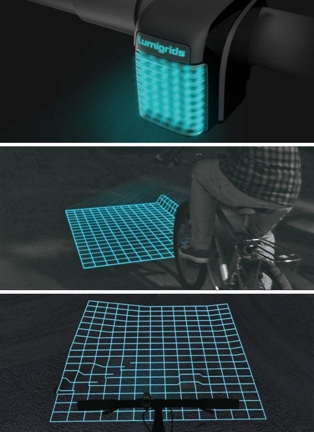
Thoughts have been swirling around in my head ever since I saw the recent Tested video. We all saw how the actual cutting deviated from the drawing on the material being cut. I thought to myself, what is to become of the pass-through feature if the Forge can’t use the lid camera to accurately align a new cutting session with the edge of what was previously cut?

@sam had a very insightful comment:

So it seems like there are three separable issues that must be tackled to get pass-through cutting to work.

–correcting for the distortion of the wide angle lens
–accurately measuring the thickness of the material (and adjusting the distortion correction accordingly!)
–accounting for material warp

I was curious to do some computations to see just how much error in cutting there would be if the first two issues were solved perfectly, but the material is warped, using realistic dimensions and expectations for the warped material.

Getting someone to provide actual warping data proved to be tedious :grin: , so I decided to just treat it as a variable.

Suppose the material has a saddle-shaped warp to it, which is much more likely to happen, I’m guessing, and will give conservative results compared to bowl-shaped warping.

Now, imagine a section view of the material, with the cross-section line passing through the point where the depth sensor is making its measurement and one point where the material is resting on the bed. For simplicity sake, let’s assume this section forms a flat cross section. I know, very unrealistic, but suitable for this very rough approximation.

Here’s the situation:

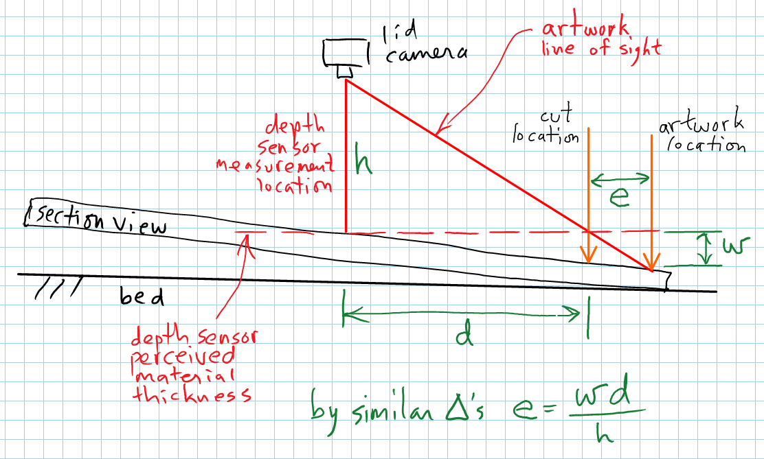
Let’s put in some typical numbers. The distance to the lens, h, is roughly 5" (thanks @marmak3261 !). A typical value for “d” might be 10".

That means the error in cutting, e, will be about twice the amount of warp, w, as measured in the drawing. That’s a lot.

My take-away from all this is that unless the Forge uses the camera in the head to characterize the shape of the material surface, and uses that information as part of the lid camera distortion correction algorithm, I see little hope of pass-through working satisfactorily on warped materials.

Furthermore, this problem also applies to the accuracy of the simple act of cutting artwork captured by the lid camera, and aligning it with existing features on the material. This, in itself, may be more important than the passthrough issue!

Don’t get me wrong. I’m still very excited to receive my Forge, even if it has this limitation. I know there are brilliant people working on this problem at Glowforge, and for all I know, already have a solution! May the Forge be with them! And also with you, soon.

11 Likes

Maybe I am understanding is wrong, but the depth sensor is not in the lid camera. It is in the head camera. Wrong? - Rich

1 Like

Yes, I know. But I’m making the assumption that it only measures the thickness of the material once, and that takes place at the position identified in the diagram.

3 Likes

Really interesting to see your analysis :slight_smile:

I would speculate that we will see the macro camera used for scanning artwork and passthrough cuts in the future since it allows for much more accurate results. None the less, correcting for warped material is still a difficult problem to solve since there really isnt a “right” solution. It depends heavily on what the user plans to do with it. For example if they need square cuts then they really need to start with flat material (unless GF has an unannounced feature allowing it to cut bevels!)

Long term I don’t see any reason why passthrough couldn’t work as advertised, but it will probably always require the material to be flat if you want accuracy

4 Likes

Currently, yes, but I believe the Dan said it has to do with auto focus not being implemented yet.

3 Likes

No, @takitus speculated that was the reason, and @dan said that the depth sensor was working fine.

1 Like

theyve said it accounts for curved surfaces. not to mention if they cover proofgrade materials with a mesh of UV QR codes they can use the camera to see if that mesh is distorted in any way and get a general distortion map to tell the head camera where it needs to check, or even just calculate the warpage by itself. Double checking with the head cam would obviously be best.

3 Likes

That’s an interesting idea.

Edit: it would, however, lock us in to using proofgrade materials

I said somewhere that the depth sensor was disabled in the tested video, because thats what they said in the video. Turns out its not disabled, it just doesnt work because the software is incomplete. The end result is ultimately the same in the sense that somewhere between the sensor gathering depth data and the trace function trying to determine scaling the two arent able to communicate causing it to go to a default depth/size based on default bed depth. Again this is partially speculation, but Im pretty sure its correct.

1 Like

Maybe I’m not using the correct term with “auto focus”. Yes, I remember he said it was working, but it doesn’t handle curved surfaces yet.

Bah, takitus beat me to it.
interesting with the mesh. Imagine if we could print our own meshes on labels on the old ink/laserjet…

1 Like

I assume you are referring to the original specs that says the Forge can etch on curved surfaces. That’s a very different issue than correcting camera-captured artwork for cutting on a warped surface. One deals with adjusting the laser focus locally. The other is a global adjustment.

1 Like

I like the fact that you’re thinking/asking about this too!
my assumption was that they did have this all worked out and are either debugging the related software or are waiting for appropriate patents to get approved so they can release it. If that isn’t the case, I guess I’ll have to make sure to send my pieces through the planer a few times right before lasering. Another thought I had was to project a visible grid onto the work piece so that the camera and system can recognize any changes and correct it. But then I realized how “old school” that tech is these days. We have mini Lidar units now! Like this: https://www.sparkfun.com/products/14032
The one in my Structure Sensor is way better, but a lot more expensive.
Maybe if you have a super curvy piece that you need to work on with super accuracy, in the future you could swap out that head for a Lidar head and map it before starting.

4 Likes

Like the bike laser grid!

13 Likes

Yeah! That’s exactly what I was envisioning!
The first one I built for my school was like this:

then we got this:

now we have this:
http://structure.io/

4 Likes

aye, i have one of those. pretty cool. not very high res, but enough to do cool things with:

17 Likes

Out of likes, that is sweet!

1 Like

I remember thinking that was the coolest thing ever. Did it ever make it to market?

1 Like

I don’t know. I remember being super excited about it until I got injured rendering my bike riding abilities null. I think it did

2 Likes

you can still buy the structure sensor, it’s still being developed (software wise).
I think there was a weird, possibly failed partnership with these guys:
http://www.3dsystems.com/shop/support/isense/videos

Even with the macro camera and multiple-point depth sensing there’s going to be some limit to how accurately you can trace unless you’re willing to spend NASA-style amounts of processing time on your images. (You could take a new macro picture every few millimeters and turn that into stereo pairs and get a complete depth map, but at 5 megapixels the square inch…)