I dont know enough about reading SVG “code” but I opened the original shared SVG file with a text editor and it says the file was created in CorelDRAW X7 so now there’s another level of file handling at issue. From what I can tell, there is no binary info. Looks mostly like X,Y coordinates.
Sorry I wasn’t clear. When I open the design. It all looks like a black dog with white bones in Inkscape. But when I open it in the GFUI it’s all black, no bones. That leads me to conclude that the white is not a knockout but a white fill overlaying a black fill. White is a color so as a fill it will be engraved and show up as shaded to be engraved.
So back to Inkscape to check it out. When I break apart the object to get at the bones, then it makes all black bones and all black dog. That’s just the choice that is made when you break up a compound path that is two distinct colored infills. One will dominate the resulting bunch of objects, at least that’s how I see it happen in Inkscape. It is a pain in the neck to deal with this when you are converting texts to paths. It’s all ok the first time, but if you break it apart too much, then all the counters/spaces inbetween letters like As and Bs and 8s et cetera get filled black because you have broken the compound path.
Try it sometime in Inkscape with text converted to path. Break it apart to get at the individual letters to tweak. Then if you try to recombine the text as one path for keeping it together for a wide raster engrave and then uncombine it, you have to do each of the letters with counters individually to put the holes back into them. The Scabble tiles were so much fun!
So it’s back to the single most important part of this discussion: If you don’t want something to be engraved, you just leave it alone with no fill. If that something is in the middle of an object that you want to engrave (a true doughnut) you have to do a boolean difference with the middle shape and outline shape.
NEW TEST FILES
I decided to try and pinpoint the issue by making a new, simple file. It’s a long post, but wanted to be thorough. I still can’t tell if this is a Corel issue or the GUI and I can’t figure out what it’s causing the issue.
SUMMARY: (In case you don’t want to read the rambling below.)
I have duplicated the exact same issue of the GUI ENGRAVE not recognizing all the shapes in a combined element regardless of the steps taken to make the element (Fill/no fill/combined/grouped/twisted paths/no twisted paths etc… Of note, the shape not showing on ENGRAVE only has four nodes, all of which are correctly joined etc. and there are no open paths. Seriously, I tried 30 different combinations of creating the file. See very last pic for reference.)
I made three different test SVG files using Corel X7. I tried several different steps to get to the same final element of a rectangle with shapes cut out of it just to see if one of the steps was the issue. It’s a bit confusing, but I’ll try to explain what I did in each file. Sorry, this is pic heavy as I do better with pics than words. ![]()
I have attached the SVG files in a zip file and taken screen shots on how they all appear in the GUI. The elements were made by combining/joining four smaller shapes with a larger grey rectangle. The words you can see in the files were converted from text to “objects”. There are no overlapping or errant nodes etc.
TEST ENGRAVE KITTSKI 1.zip (1.9 MB)
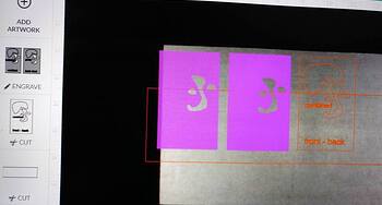
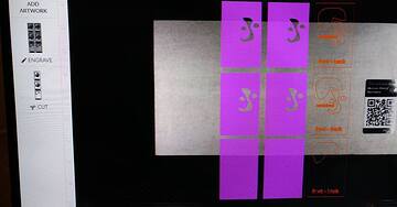
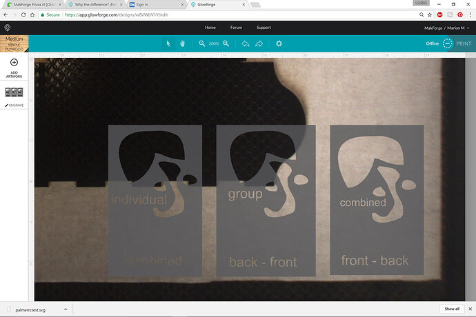
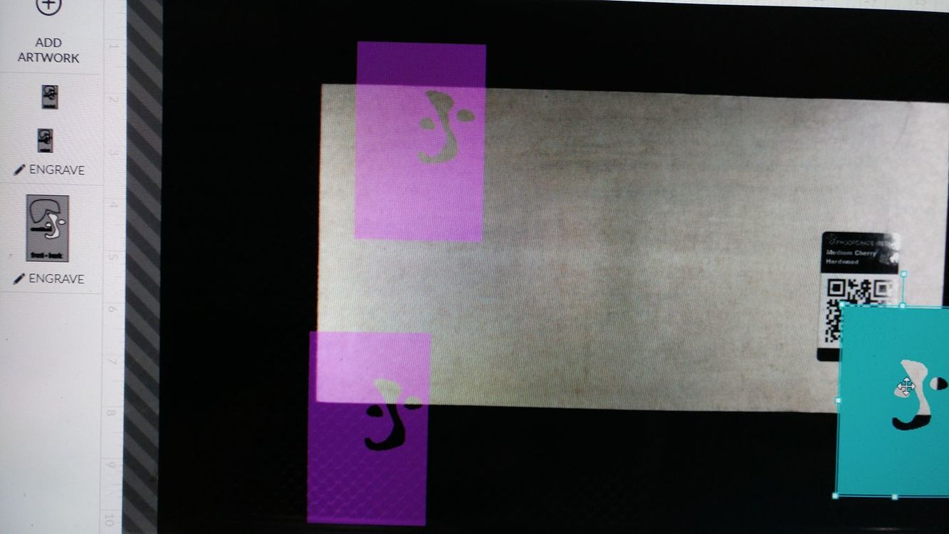
Another weird issue I found when doing this; for some reason the GUI is grouping two of the three elements together. It is taking three separate elements and importing them into the GUI as only two separate elements. I have tried three or four different file changes and can’t get the GUI to recognize them as three separate shapes. (The two elements are not grouped in the original file, only showed that way in the import.) In this example below the elements were placed far apart in the file itself, but it still grouped two together when imported to the GUI.
File TEST # 1
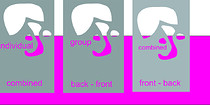
Steps taken to get the three different grey elements you see in the below pic.
**-The first pattern on the left had all the individual pieces “combined” together to subtract the smaller shapes from the rectangle.
**-The second middle pattern had all the four smaller pieces grouped and then they were placed in front of the rectangle. I then used the command to “back minus front” to combine the grouped objects with the rectangle.
**-The third pattern had all the smaller pieces “combined” into a single element and then they were placed in front of the rectangle. I then used the command to “front minus back” to combine the now single white object with the rectangle.
I placed pink rectangle in the file to show that all the elements were combined correctly and the smaller shapes have no fill.
The results of all three files were identical with the same larger shape (and the words) not showing on the GUI during the ENGRAVE, but showing for a CUT or SCORE.
This first pic is a JPG of the FILE in Corel X7 . Below 2 pics of it imported to the GUI
(For all that is holy, please notice in the first pic that all interior shapes have NO fill so that is not this issue with the engrave! ![]() )
)
file TEST #2
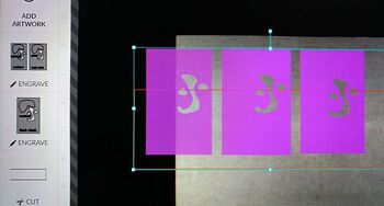
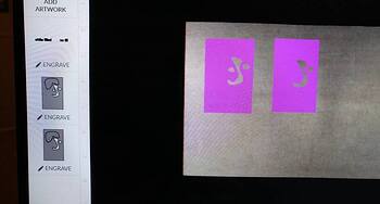
Basically the same file done a bunch of ways that I can’t remember now… Of note, see the bottom row. I saw that the larger shape would not show during the ENGRAVE, so I deleted everything else in the element to see if it would show on it’s own … Still nope
Two below pics show the imported file in the GUI
file TEST #3
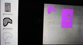
**-The first pattern was with the rectangle filled grey and the other elements filled white.
**- The second pattern was with the rectangle filled grey and the other elements with NO fill.
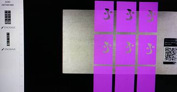
Below pic of this file…still nope
The last test…
I separated the larger element that isn’t showing during the engrave and made it it’s own shape just to show it was a closed path with no issues. I duplicated it THREE times; one with fill/no outline, one with outline/no fill and the third no fill/no outline. I left the original pattern for reference. The GUI doesn’t recognize the third shape with no fill or color at all.
EDITED TO ADD
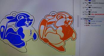
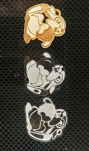
FWIW, I have now tried about five unrelated SVG files and have gotten the same issue with the engrave in the GUI. I made this Thumper file last night. I first traced a drawing, cleaned it up and made the blue image. I saved the blue version with the outline and the file worked perfectly. I was able to select ether cut, score of engrave on the two separate elements (outline and blue shape).
I then wanted to do a reverse version and made the second orange Thumper. I made a copy of the blue image, broke it apart and recombined it to make the orange version. As you can see in the pic of the file in Corel, the blue and orange elements are just one object each and the engrave areas are not filled. (The yellow is just to show the transparent areas and was not part of the file uploaded to the GUI.) Sure enough, the new recombined version would only engrave one solid object. I had to save the outline as a SVG and then save the orange part as a JPG and “add” it to the GUI and set it to engrave.
It is only a single path statement with a black fill in the SVG. The bones are holes in the polygon, so they don’t get any fill. In the GFUI they will only show white if you put some white material on the bed. @Jules’ second screen shot of it looks correct with purple where it will engrave and what the camera sees where the bones are.
Does this work for you?
<img src="//cdck-file-uploads-global.s3.dualstack.us-west-2.amazonaws.com/glowforge/original/3X/e/8/e81dc87e8f2c200fb41a721964867d494448567c.svg" ">
I removed the rectangle and pulled it into OpenSCAD and extruded it to 3D. That told me it was non-manifold. I.e. there must be gaps or self intersections somewhere. When I expanded it by 0.01mm it fixed the issues.
offset(0.01)
 scale(25.4/1000)
import("test 1.svg");Okay, I didn’t realize you were trying to create these things in CorelDraw. That isn’t a program I currently have installed, (or am familiar with - I ran out of time before getting into any CorelDraw tutorials) so I’m not going to be able to give you any quick specifics on how to fix it.
Having said that - you first have to convert any text into Curves before you can use it in the Shapes manipulations. @johnwills has a tutorial for it in the Matrix:
Another thing I picked up from what you typed above - you are using the Combine tool to try to subtract your shapes, and I’m pretty sure that’s not the correct tool from what I have been able to discern in CorelDraw. You need to be using the Trim tool under the Shapes menu. That seems to be the equivalent of the subtraction tool in the other 2D vector programs.
There are a couple of video tutorials linked in the Matrix for how to use them, and one on the difference in treatment between Combine versus Weld so you can see what’s happening.
See if doing those two things doesn’t move things along a little better. ![]()
Regardless of the tools used to create it. The SVG is simply three path elements that are filled plus a filled rectangle. Each path is described by lines and Cubicbeziers. Depending on the winding order closed paths either describe the outline of the shape or the holes in it. There is no text, just text shaped holes.
Two of the paths are one shade of grey and the other a slightly different shade so that is why two are grouped and the other not in the GFUI.
When OpenSCAD reads it it converts all the curves into short line segments because there are no curves in OpenSCAD. I don’t know if that is what makes it easier for the GFUI to digest or whether it can’t handle self intersections or tiny breaks.
I’m seeing a pattern forming here, thanks to Thumper!
It appears that the GF software is simply having problems rasterizing engrave patterns for vector artwork that contains “islands” - areas that will have no engraving, that are completely surrounded 360 degrees by areas that are engraved.
Since the GFUI has to interpret the vector art and produce bitmap data in order to engrave (ie: ALL engraves are rasters, no such thing as a vector engrave) the easy way around this is to take care of the rasterizing in the design program.
You don’t need to export a separate bitmap file though then recombine in the GFUI. Once your paths are setup in the design program the way you want them to appear, there should be an option somewhere to make that engrave vector into a bitmap (it may also be referred to as rasterize). Example, in Inkscape I would select the orange vector of Thumper, right click and choose “Make Bitmap Copy” That will rasterize that element and leave it right in place in the layout, it also maintains transparency so everything else “behind” it shows as normal. Inkscape also happens to create a new PNG file of that element in the background, handy feature if it’s needed again. I’m sure CorelDRAW has a similar function, it’s been 8 years since I used it though and can’t remember where it is or what it’s called. It’s there, though.
That gives you the control you need without adding more work putting things together in the GFUI.
That’s perfect! Makes me want to keep working with OpenScad. The ability to do parameters in the sketches is very helpful.
Great, so the GFUI has no problem with islands with holes in them when they are closed loops of line segments. Something is going wrong with interpreting the Corel format but InkScape and OpenSCAD get it right.
What matters for engraving to the GFUI is fill versus no fill (empty). How the different programs treat “islands” inside of a fill has a great deal to do with how it is interpreted by the GFUI.
That’s a two sentence explanation of why people see so many problems. Each program has a correct tool to punch out an island area inside of fill, but not everyone knows where to find it or how to use it.
The GFUI handles self intersections - it will engrave wherever it sees fill. If you are cutting along a path, it just follows the path, and will self intersect where it crosses.
What doesn’t really help is telling folks how to do it in another program, because that will generally just confuse the hell out of people. So I try to tailor helpful suggestions to the program being used to create the file. I thought she was using Illustrator and that was my (bad) assumption. It wastes time for both the person being helped and the helpers trying to assist. I screwed up.
Anyone wanting to help needs to get into the habit of asking which program people are using before telling them how to fix it. There are just too many options for this.
This isn’t about using OpenSCAD or Fusion 360 or Inkscape or Illustrator - whatever people want to use can probably be made to work with this interface - it’s pretty flexible. But there are a few rules, which are listed in the first tutorial in the Laser Tutorials Matrix. That is a very important tutorial for everyone to read if they want to understand how to make their vector designs work with the Glowforge.
(And it doesn’t matter how good you think you are with your design software, or how much you think you know - you should probably take the time to read that tutorial in order to understand how to make your designs work with the Glowforge. It’s very high level and applies to all of the design software.)
Just wanna say… This thread has been a really interesting read! Thanks to those contributing to it!
What I am trying to convey is the SVG file is basically correct. There is a bug in the GFUI or there is something slightly wrong with the file that upsets it. OpenSCAD correctly interprets it as rectangles with text shaped holes in them. So does InkScape. When I examine the file that is what it is.
The islands inside the fill are simply loops in the path that go in the opposite direction to its outline. That is the only way I know of correctly representing holes in an SVG file.
I will knock up a program to check if any of the loops have tiny breaks as that would explain why it looks correct but wont raster engrave.
Okay, you do that.
I currently have my old computer fired up, on which I have CorelDRAW 11 and Illustrator so I can work quickly between the two. I’m pulling together some screenshots of what I’m doing but right now those are on the other computer and I have to email them to myself because these boxes just are not talking to each other over the LAN. I’ll come back later and add the screenshots, or maybe not, other than being visual illustration/proof, they don’t lend much more new info to the discussion. Anyway…
Right now, I am seeing absolutely NO, none, ZIP, zero good reason that @kittski’s CorelDRAW generated SVG is not working as expected.
When viewing the file in CorelDRAW, the software is reporting that all curves are closed. The colors of all the items are the same, except the box at far right which is a different shade of grey as @palmercr pointed out however that should not affect how the engrave fill behaves on the far left or middle versions. The additional color would only create an addition operation in the list in the GFUI.
@Jules CorelDRAW has a few options for knocking out islands. The “Combine” command in Corel is equal to the “Make Compound Path” command in Illustrator. Corel has a “Shaping” palette which is equivalent to Illustrator’s Pathfinder, and contains a “Trim” command equivalent to Illustrator’s, as well as “Back Minus Front” and “Front Minus Back” which are like Illustrator’s same commands. Any way you choose, you get the same visual result in CorelDRAW with the islands knocked out properly, however NONE of them give the proper result when opening in Illustrator, and based on what’s been presented here so far, probably still not right in the GFUI.
It’s also worth noting that with this file opened in Illustrator, If I add my own text in place of @kittski’s and try to use the Compound Path command in Illustrator, it will NOT work, and there is absolutely no reason it shouldn’t. I have to use the tools in Pathfinder to subtract my own entities that I’ve added and that is not proper behavior for Illustrator.
Something wrong! Very wrong! to be continued…
Interesting @palmercr. That fixed the GUI recognizing all the shapes in the rectangle. I don’t understand why the GUI recognizes the other three shapes and not the fourth. I would think it would be an all or nothing if there were an issue with the rectangle. I also don’t get what happened to create the error in the rectangle. It was a four node shape and a pre-made shape so it’s weird that it was either faulty from the beginning or was corrupted from the combining with the other shapes.
Your fix illustrates another issue too. (It very well could be something I don’t understand yet.) All three elements in your file will only load as one single element. It should let you select different rectangle and assign an independent tasks (cut/score/engrave.) I broke your three rectangles apart and combined them again into three separate elements. They still loaded as one object. I then put each rectangle onto it’s own layer and it still loaded as one. I saw this same issue with the original test file, but it loaded three objects as two.
@Jules the text was converted to objects prior to being combined. The “combine” is a correct option to remove one shape from another. I also used two other boolean join options as well, all produced the same results. It really shouldn’t matter as all combined all the elements into the same identical single objects
Nice observation @mpipes !! I think this is looking like a GUI issue and maybe not on my side. I used your solution of importing a raster to engrave, but it really should work correctly as a SVG. For someone like me with a lot of intricate art, it really is cleaner and easier to have just one step. It’s driving me nuts trying to understand what’s happening. I think you really might be onto something though!
I’m off for my 12 hr work day and I’ll check back on this tonight. Very interesting discussion!
The GFUI groups by colour only, it ignores layers. OpenSCAD can only export one colour at the moment so mine are all grey. To get three groups you need three colours.
Ahh, that makes sense, forgot about the color assigning done by the GUI. Will play with it more tonight.
I might be incorrect, but my understanding is that in CorelDraw, the Combine option keeps the original attributes of the part so that it can be broken apart again later, which means that it is still capturing the Fill information. Once that is exported into the SVG, it is still being seen by the GFUI, which picks up everything it sees.
If someone with CorelDraw would just try the Trim option, it should be easy enough to see if it is still picked up in the GFUI, or if it does what has to happen…complete removal of the shape from the interior. 
Oh snap! I get my GF today, perfect timing to help suss this stuff out and getting that GFUI as the final piece of the puzzle.
Now I’m going down a rabbit hole with Illustrator. I don’t get this behavior. I draw my own text and my own rectangle and I can knock out the text with Make Compound Path. I make my own text and my own random blob shape, I can NOT Make Compound Path. I make new rectangle and new text but the rectangle touched the larger curve of @kittski’s, I can NOT Make Compound Path. Bizarre!
