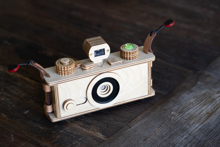
Hooray, it’s Worldwide Pinhole Photography Day! And just in time is the second prototype of my 35mm format pinhole camera! The first one was a big breakthrough for me, but there were some issues that came up during production and in the field.
The first issue to be addressed, if you recall from the original writeup, was that the tolerances were way off, causing the axes of the film transport spools to be off-center. This was “fixed” by creating a special top plate that compensated but it was a far from a perfect solution. This issue was forefront on my mind when I made the improved version of my 120 camera. The solution was to use square registration pins made of 1/8” plywood. It worked very well on that build so I implemented the technique here. This time there were also cases where I needed to align three layers, so the values needed some more finessing.
After several tests I came up with the right numbers to get everything to fit just right. The result was perfect alignment on all layers: top, bottom, sides, front, and back. I am so happy this works ![]() .
.
The second issue, which was noted in the original write up and solved in the stereoscopic camera build, was that the 1/8” plywood shutter was too thin to block the light. This was eventually backed with lightproof material but it was too late to add this to the original 35mm camera. I tried staining the shutter with India ink but I could tell it was not thick enough. Consequently I had to keep the lens cover on until right before I took an exposure, rendering the utility of slide shutter somewhat pointless. I took several rolls on a recent trip to Japan and saw that if I got a little cavalier and left the lens cover off, I would indeed get light leaks. Well, more like light seeps - faint trickles of light seeping through the wood over time.
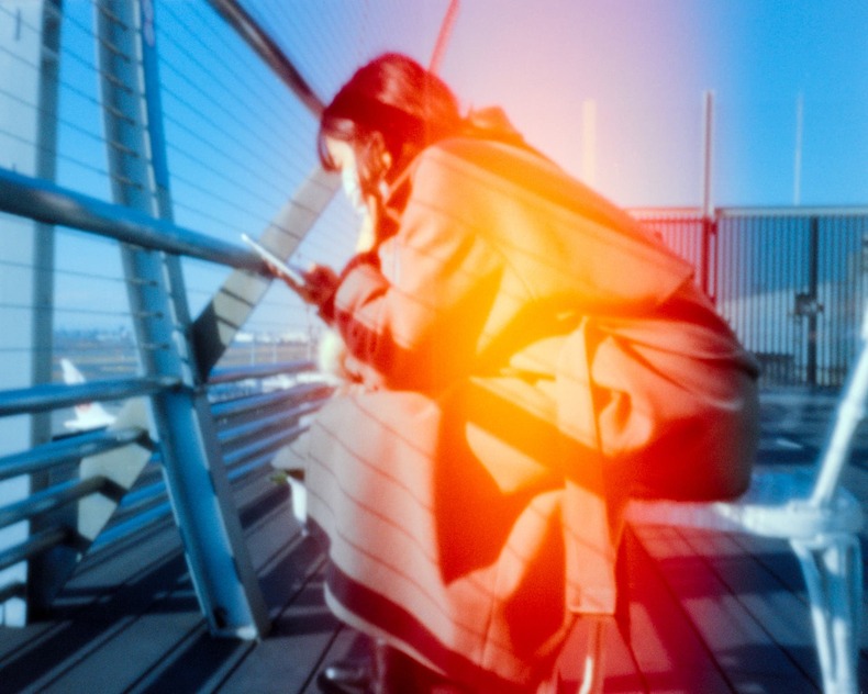
Sometimes it made for some interesting shots, but this is not generally desirable. So for this build not only did I make the shutter lightproof, I took extra care to make sure everything was light tight.
The third issue was strength. The original acrylic parts were prone to snapping, especially the rewind knob. The rewind knob was replaced with thicker Delrin and the advance knob was replaced with brass rods.
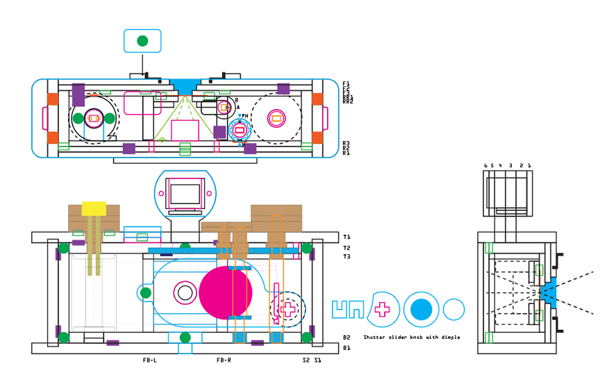
ONE BIG CHANGE (okay, two and a DISCLAIMER): After I completed the camera I realized that the slide shutter was just too tight. Sooooo… I had to do it ALL OVER AGAIN. I was so displeased at myself that I added a viewfinder feature to justify a rebuild. Many of the following photos were taken during the original build so you won’t see the viewfinder. I did the rebuild so fast that I barely took any pictures. I only snapped a few shots of the viewfinder toward the end of assembly. But here is the basic schematic of the final build.
Another feature I added (to pretend I rebuilt the camera on purpose) was half frame capability. Half-frame cameras were popular in Japan the early 60’s as it doubled the number of exposures on a roll of film by splitting the normal frame in half - hence the name. Film was still expensive for many folks and this drive sales of cameras like the Olympus Pen.
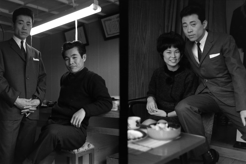
Two half-frames on a single 35mm frame. On the right, my parents circa 1964.
My parents had one. Of course this mean you have to enlarge the picture more than you would a full frame negative so image quality degrades somewhat so this fell out of vogue. But half frame has made a resurgence in recent film photographer circles because film is now more expensive than ever and the default format of half frame is portrait - that is to say vertical - so you don’t have to rotate the camera 90˚ when you take a picture of a person. This also justified the addition of the viewfinder - double win!
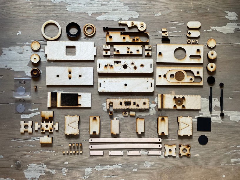
The “class photo” of all the parts (sans viewfinder).
The build went really fast. The alignment pins took all of the guess work and finessing out of the glue up. The subassemblies formed up very quickly and this gave me time to iterate upon smaller details while I was building.
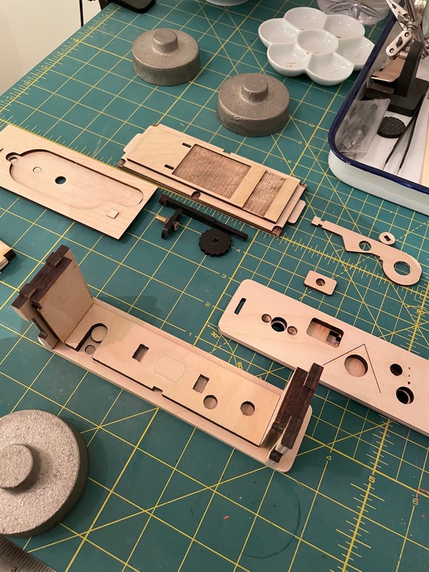
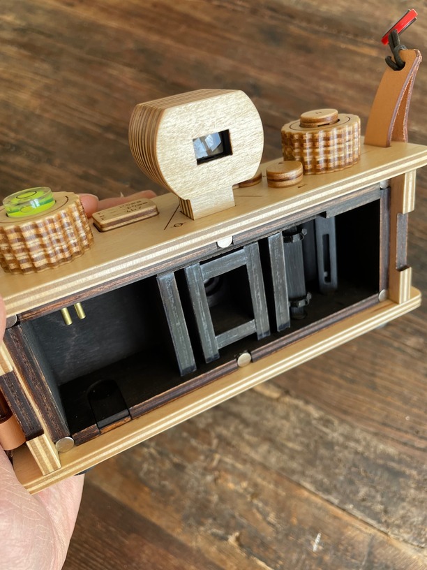
The transport axis lined up perfectly. The film transport system is wicked smooth now! I added teflon tape to the frame walls. Since the film drags over this surface it is good to have this as frictionless as possible. On all of my previous cameras (except the panoramic 120) this was left as raw plywood. Sometimes I would notice long horizontal scratches on the negatives which I assume to be the film emulsion scrapping against the wood. Why it happens sometimes and not always is not known but I thought I’d give the film some added protection with the teflon. I think this benefited the smooth operation of the film transport system as well.
The evolution of an idea.
I wanted to improve on the film type indicator. The magnetic tabs certainly worked well and it was quite handsome but I discovered that if I ran out of film while on the street and went to buy more, sometimes the available films were not the ones I had made tabs for. I would have to substitute something close and make a note of it on my smartphone. Another situation which was not covered by my existing film tabs was pushing or pulling films. What’s that?
Pushing, in film photography is when you underexpose the film and then over develop it during processing. Pulling is the opposite - you over expose and under develop. You can push film quite a bit - I pushed ISO 400 film to ISO 3200 this past trip with great results. The trade off for this added sensitivity is that you end up with less shadow detail, increased contrast, and increased grain. But that can look cool! Also, for pinhole photography, since the aperture is so small, faster film speeds mean you don’t have to keep the shutter open for minutes or hours on end. I wanted to take shots with this camera without a tripod so ISO 3200 works great. In daylight I can get exposures for less than a second. That’s comparable to a lensed camera! But how do you indicate that the loaded film is being pushed or pulled on the camera?
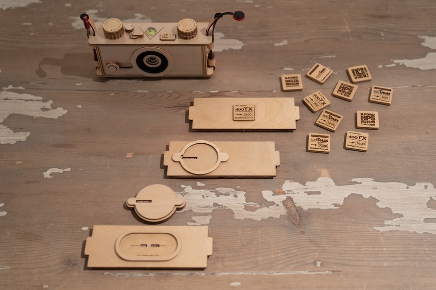
You can make more tabs, which I did.
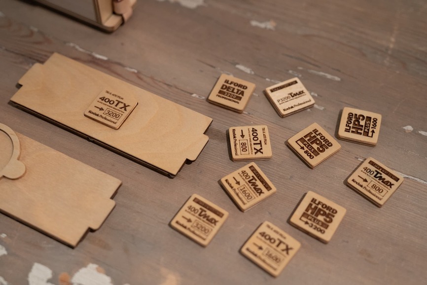
Here I made tabs for Tri-X, T-MAX, and HP5 with different ones for pushing to 800, 1600, and 3200. I also made tabs for films that were already at 3200. But this gets unwieldy. How many of these tabs am I supposed to carry around? What if I change rolls in the field? I’d have to bring the films and the corresponding tags. What if I buy film while out? I’d have to bring the tabs of the likely films I’d able to buy. It gets absurd - I’d have to walk around town with a bag of tiles jiggling around my bag! Eventually I will settle down on one type of film and know it inside and out, but for now I want to experiment and remain flexible.
Idea 1: I made an indicator that was made of concentric discs.
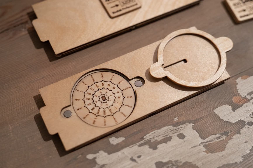
The film type was on the outside, the native film speed (often called box speed since that is the ISO rating on the box) in the middle, and the push/pull factor in the center. They are toothed in such a way as to prevent them from moving once set. A cover reveals the setup and hides the other text. This looked great - BUT - there’s always a but. This created gaps in the camera back.
I tested it and it proved to be light tight but my goal was to leave nothing to chance in this regard.
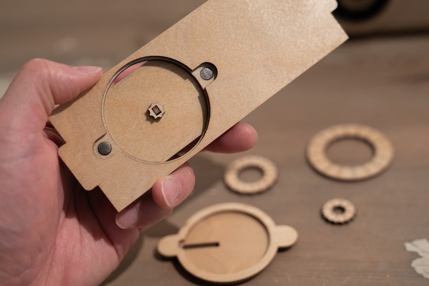
Idea 2: I took the set up from the first idea and made it an external attachment.
It had a plug that would fit into the recess of the camera back that used the tabs.
I thought this was pretty cool - BUT. Again that but. It made the back of the camera thick. It does not look bad at all but the back of the camera is what is constantly bumping into your body. I could imagine it getting annoying if I had to walk around with it all day - not to mention the possibility of knocking the thing off.
You might be thinking, why not just make it smaller so that it does not make the gaps? At 5pt. the text is already tiny. If I reduced the disc size then the typeface size will also need to be reduced and that would be too small for me to read, and even if I could, such a small engraving will not hold up detail on plywood for very long. So…
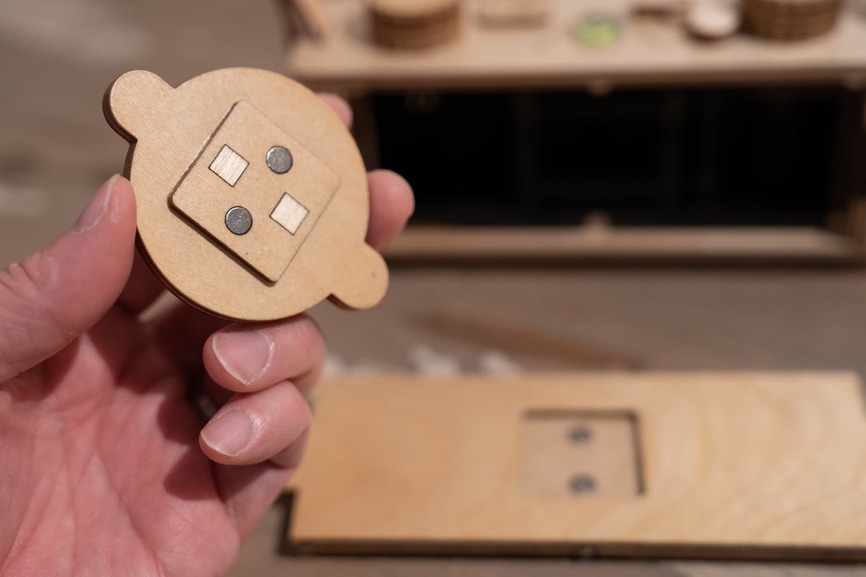
Idea 3: I decided to put the film type on one disc and the ISO and push/pull factor on a second set of discs.
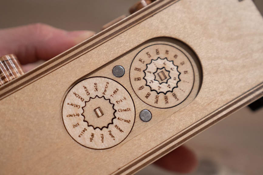
They would form up in the middle and create a single line of text.
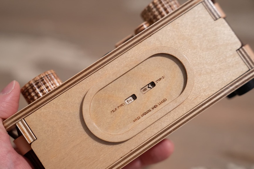
There’s a small gap between them but this was acceptable. Now I have something that is flush to the camera back, lightproof, and legible. This example shows Tri-X, which has a box speed of ISO 400, being pushed 3 stops (400—>800—>1600—>3200). This would indicate that I have Tri-X pushed to ISO 3200 loaded in this camera.
As far as the data on the gears go, they include almost all of the film types and ISO ratings currently available in most retail stores that sell film. Sure there are some exotic films out there, but nothing that you would encounter in a shop somewhere. This will work for quite a wide range of situations. If there is a film that I discover along the way that I really like, I can always fire up another gear that includes it while I strike off a film type that has fallen out of favor.
Something I discovered after taking several rolls with the first prototype was that the field of view was just not wide enough for me. At 30mm focal length you’d think that would be plenty wide, but I’ve been using a 15mm lens on my lensed camera and really fell in love with that aesthetic. It really lends itself well to street photographs of Tokyo.
Taken with my Voigtländer Super Wide-Heliar 15mm f4.5
On this camera, I decided to shorten the focal length to 25mm. This created an issue. The ideal pinhole aperture for a focal length of 25mm is .18mm. Unfortunately the vendor who makes my precision etched pinholes does not make .18mm. He does .2mm and .15mm. With larger formats .2mm should work fine, but since 35mm negatives are so small, any and all imperfections get magnified. An aperture that is too large causes an image to be blurry because more light rays from more positions makes it through the pinhole - an effect known as geometric blur. If the pinhole is too small the image gets degraded from the effects of diffraction. In simplest terms this is when a wave of light hits the edge of the pinhole and causes it to “bend” and propagate “ripples.”
I calculated the optimal distance for a .15mm pinhole to be about 17mm. Can I just make the focal length 17mm? Ideally yes, and I hope to someday but that will require a different configuration to what I have now. For this iteration, I’m going to keep my target distance to 25mm. Now, 17mm to 25mm seems like a bigger gap than 30mm to 25mm but effects due to diffraction are minimal compared to geometric blur. I checked to see what commercially sold pinhole cameras use, and apparently many manufacturers have updated their 35mm format cameras to use .15mm pinholes at 25mm focal distance. Interesting. However, many veterans seem to like .2mm pinholes for the same distance. Hmm… also interesting. Looks like I need to try both out for myself and determine which size suits my aesthetics.
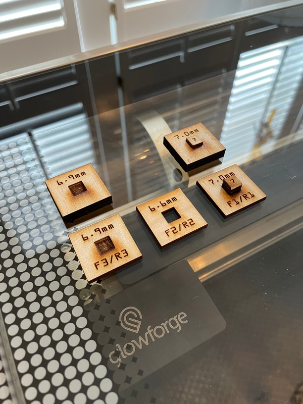
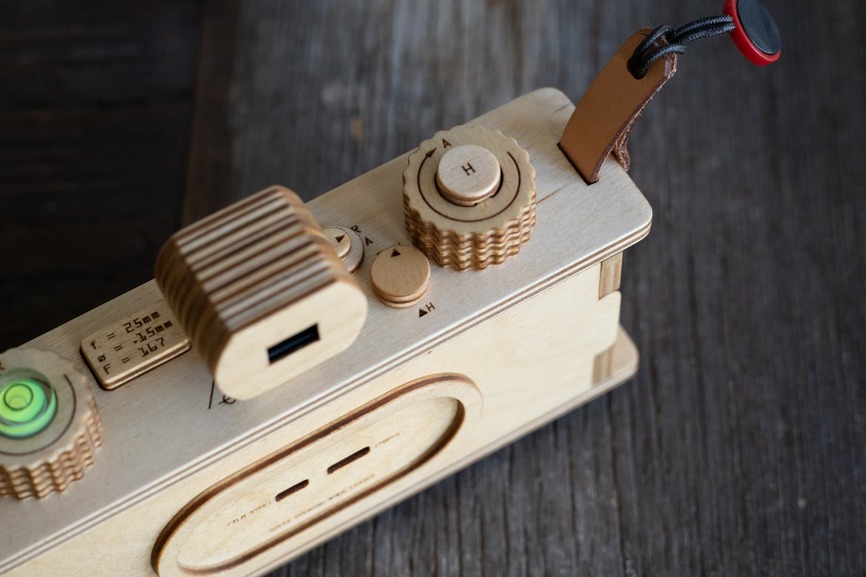
The pinholes have been replaceable on all of my cameras since the beginning, but if I change the aperture of the pinhole, the pinhole data, which is engraved on the top plate would not reflect the change. Easy fix: make swappable pinhole data tabs like I did for film types.
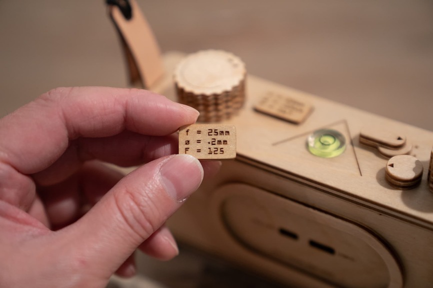
This is important because the F stop value of the camera will be different since F stop is a ratio of the aperture diameter to the focal distance. A .2mm pinhole gives me an F stop of F125 and a .15mm pinholes give me a value of F167. Not something I can remember off the top of my head, so it is good to have that information on the camera.
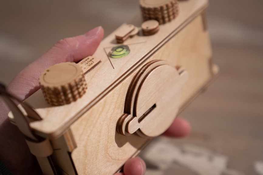
A small improvement was made with the knob I use to pull the sliding shutter. So instead of being just a flat disc…
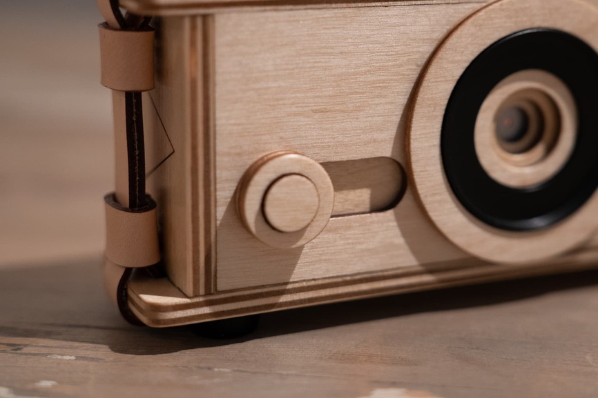
…I added an elevated piece in the center that will give my finger a little added “grippy-ness.” The shutter is super fast now.
The area inside the filter ring was narrowed to provide extra light leak protection.
The resulting stepping of the front layers should provide minor flare resistance as well.
A very minor visual change is the lack of exposed finger joints. The sides of the camera now connect to the top and bottom with mortise and tenons.
Finger joints are kind of a hallmark of laser cut fabrication and a popular aesthetic among us Glowforgers ![]() , but there was no real benefit to this and the new technique allows for a more precise fit.
, but there was no real benefit to this and the new technique allows for a more precise fit.
The half frame was achieved by creating a retaining ring with half frame “frames.” The retaining ring, as explained in previous builds, holds the pinhole mount assembly in the front of the camera.
By attaching some plywood frames, it crops the image to whatever you need it to be. Indeed I had toyed with the idea of a panoramic 35mm using two full frames but decided it wasn’t necessary for my look. So, cropping was simple. Now the frame counter had to be adjusted so that it can indicate full or half frame advances. That was really just adding a second mark at the half way point on the counter indicator on the top plate.
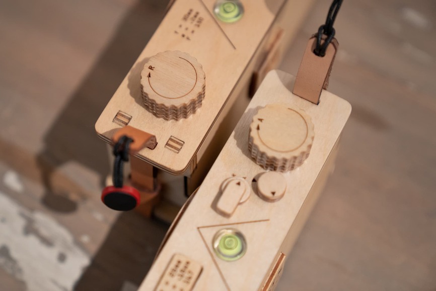
Just so I don’t forget if I configured the camera to be full or half frame, I added a magnetic indicator tab to the top of the advance knob. I thought about putting an indicator on the film type indicator, but there advance knob seemed the most logical place for it since I would see it as I wound the camera.
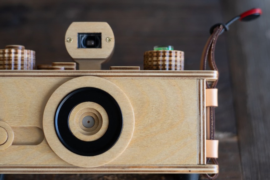
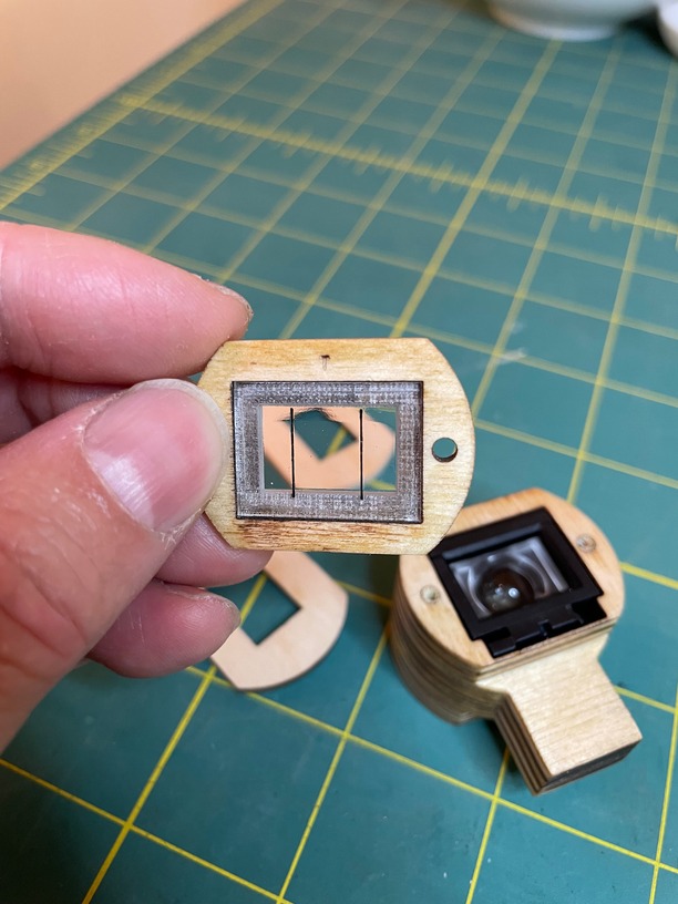
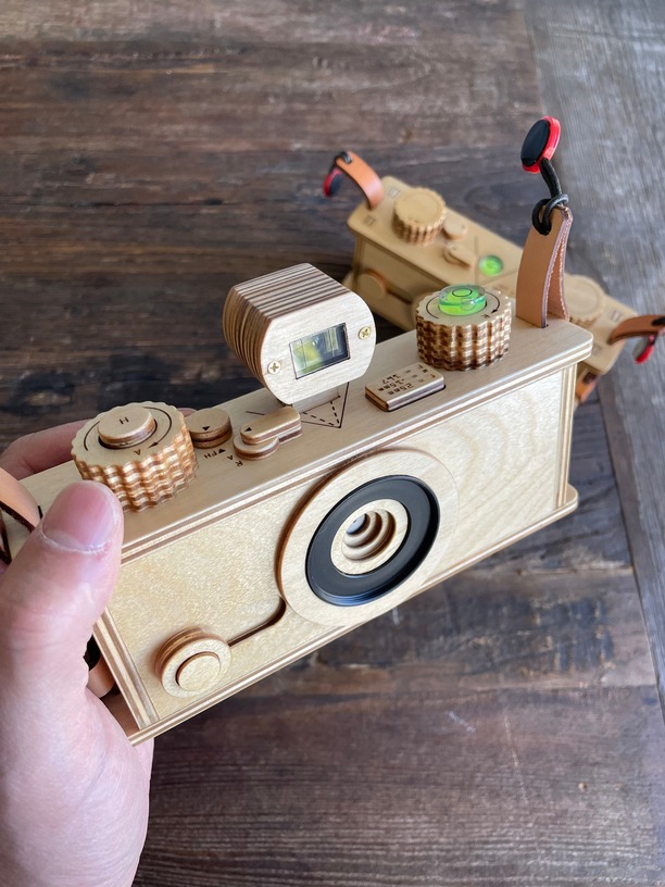
Last but not least - the viewfinder. I had been using the light ray path lines engraved on the top and sides on all of my cameras before but that was not always practical on the street. The focus (no pun intended) of the 35mm format was always speed so I had always thought about using a viewfinder just to make it that much snappier. With the half frame capability I felt it was even more important because I’d be more likely to shoot people at close range and framing them up with the lines would be a buzz kill. Plus, I look like a pigeon bobbing my head back and forth on the lines. As I mentioned I had been thinking about viewfinders before and did some research creating my own but optics is dang hard and I want this now. So I decided to just buy one instead. Now there are no half frame viewfinders commercially available but plenty of cheap plastic ones for full frame. I got one for a 24mm lens, which was close enough. I made a housing for it with concentric rings of plywood and on the front end I made an acrylic window with half frame lines engraved on the inside.
The viewfinder slid into the housing perfectly on the first try. The placement of the viewfinder meant the spirit level had to go, which was fine, on the 35mm camera I almost never use it, but I decided to move it on the rewind knob instead.
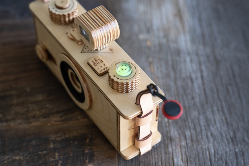
This keeps tradition alive and it balanced the frame type indicator tab on the advance knob. Could I have just mounted a cold shoe on the top plate and slid the viewfinder in that instead of building the housing? Sure, but I did not like having that cheap piece of plastic on my wooden camera and besides, where the fun in that?
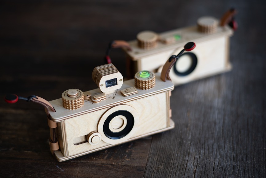
The final 2nd prototype with its ancestor behind it.
All-in-all I really like the improvements made to the camera. The 5mm difference in the focal distance meant I could make the camera body thinner by that amount and I took advantage of that. On paper it is not a huge difference but visually it changes the proportions noticeably and in the hand it fits much nicer.
I think I have reached a threshold for this camera design. Improvements to its performance and handling will require a more radical departure from the methods I am using. Some features I am considering are: an exposure counter, a push button or rotary shutter, and widening the field of view to 17mm. I am also considering ways to make the camera repairable. Currently the gear and shutter mechanisms are built into the camera with no access after assembly. This is fine for prototypes like this but eventually some kind of access to internal parts will be desirable. But for now, I’m very happy to be shooting with a camera like this.
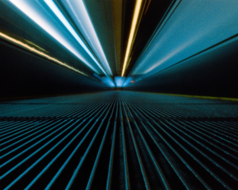
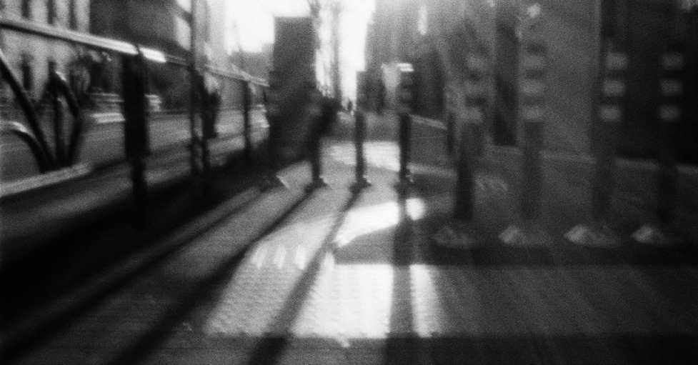
Camera placed on a moving sidewalk. The long exposure times creates the light streaks above.
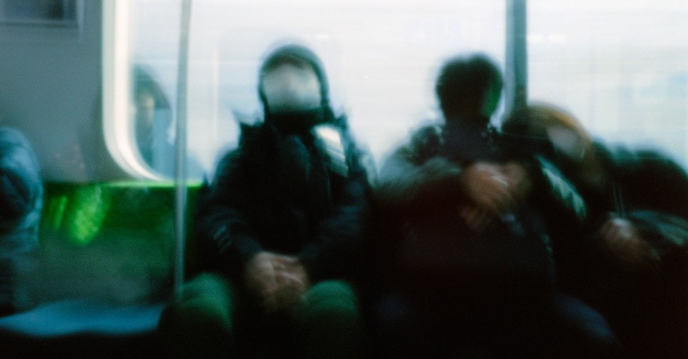
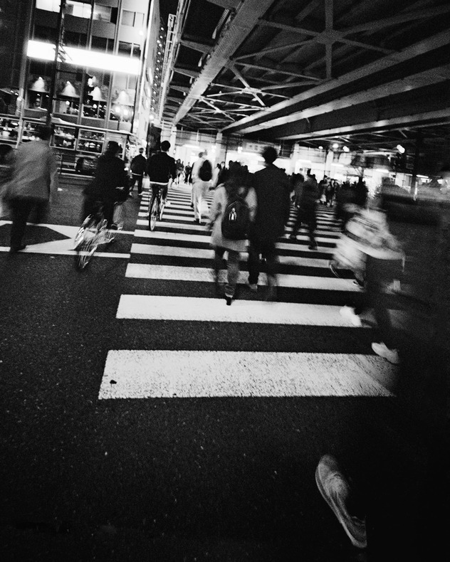
The stealthy size of the camera means I can take pictures near people.
Pushing film to ISO3200 means I can take steady shots like this handheld.
Hey, if you made it this far, thanks! My posts can be ecrusicatingly long so I appreciate you hanging around. Cheers.