Just like everyone else, my Glowforge has alignment issues. To be honest I can’t believe this is an issue 2 years down the road… I thought the camera and software was the big sell/improvement over traditional lasers?
Yes I know I can use a jig, or place it closer to the center, and making sure the material thickness is set properly (although I thought there was autofocus?) . But that costs time, money, and forces you to waste much more material.
Anyone know if they can even fix this via software, or are we pretty much screwed? Also just wanted to add this to the forum so they can see how prevalent this is.
They say they can, and I believe them. The problem has a lot more variables than some people want to admit. Hence, I am not surprised they are taking longer get it figured out.
Well the X/Y axis motors can position the beam to within 0.001". So would hope the software/camera to be able to position at least somewhere in the ball park? Accuracy without precision is a huge let down if so.
If there is no (0,0) home, I can only rely on the camera for position. It should be accurate enough so I can feel safe engraving on materials, knowing the image would at least look centered visibly…
They did show it engraving laptops in the marketing. However a 0.250" shift could have some devastating results.
Hopefully the hardware is not the limiting factor for fixing this.
If it is less than 1/4" , 0.25" at the worst place then they are calling it good for a later software fix. If it is greater than that you need a replacement.
Something you may not be aware of but none of the photos above are ,
the placement algorithms are VERY sensitive to flatness and thickness. In the pasteboard, the crease could account for all of your problem on the left. In the others, we don’t know how accurately you measured the thickness.
Try the circles on a piece of draftboard and see how it comes out. That will give you a baseline.
One last thought. For small non items, place them directly under the camera as errors multiply as you go out from the center.
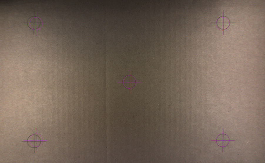
All items were measured with calipers to 0.001", thickness taken at multiple locations to check for variation. Cardboard, while it looks creased, laid perfectly flat. Made sure to check all 4 corners for any warp. I can use some draftboard, but doubt it will fix the 0.250" offset.
As to the squareness of the blue blocks, I just threw them in for about right, they were scrap parts. Regardless they were place directly under the camera, with the exact height entered. So the fact the engraving in not lining up with placement is very disappointing.
Also do you what the point of auto focus is then? I guess I am confused with the point of it…
At the moment the auto focus is used for that and that alone. placement is handled completely by the lid camera at the moment. What the future holds? Your guess is as good as mine.
I’m not calling your ability to use calipers in into question it’s just that customer service is going to ask you to do some on some proof grade anyway so you might as well go ahead and do it.
The “after” bed images are supposedly less accurate than the “before”. So if you’re trying to retrospectively see how accurate your glowforge was by looking at the post bed image, you can’t.
Why would they be at all different? Same camera, same position. I guess I will take a snapshot of the before, and super impose it on the after to see if that is the case.
I’m honestly not sure why they would be different - its one of those things I’ve seen mentioned several times, but I’ve yet to stumble across the original discussion or comment where it was learned, which might explain the reasoning.
I know @Jules reads pretty much everything and has talked about it before - she might know the reasoning behind it or the extent of off-ness or something useful.
A couple of weeks ago they told us “surprise, new camera software which uses that calibration data we collected is now available for everyone!” But, as far as I can tell, they have not promised additional work beyond what they just delivered. I have seen Support messages which include things like “as the camera improves” but that is not the same as a confirmation from @dan that we can expect more camera improvements.
Such a promise may have been made. I do try to read every post, but I am sure I have missed some good ones.
If your material height is entered correctly, and the material is flat, does non-Proofgrade material really have worse camera accuracy than identical material with the Proofgrade certification? It seems like they’d actually have to to out of their way to make the non-PG results worse since the math should be the same for each.
To clarify, the lid camera is fixed focus - it has no motors etc. With that wide of an angle, the depth of field is very large and everything in the range is in the plane of focus. The autofocus is to focus the actual beam. Right now, it takes that measurement when it scans just before a job starts. Presumably, they could take a pre-measurement and determine thickness, but that’s just speculation.
I never said or implied that non was worse. Yes, the math is the same. The difference is that often non items are not perfectly flat and we (or perhaps it is just me) make errors measuring thickness. Scraps and smaller pieces of also benefit from being placed directly under the camera. It is just how placment works.
My understanding is that the recently released work is just a first level of using that data. “As the camera improves” is exactly saying they are working on more improvements. How else is the camera going to improve?
In my opinion, they will be able to achieve sub-pixel accuracy at the edges.
Perhaps a little de-mystification might help.
The camera takes an image of the inside of the Glowforge. Support released an example of the raw image a while back, clearly showing that it sees a wider angle than is being displayed.
Take the simple case if a perfectly-aligned, perfectly-manufactured, machine.
When the Glowforge calibrates, it is taking a picture of the top of the head, very close to the camera. Thus, the logo is huge in the picture. This allows them to very accurately associate the position of the head with what the camera sees.
The image processing software transforms the picture this perfect machine takes of the bed into a flat image to be displayed on your computer. The pixel data from the raw fisheye image has its highest density directly under the camera and gets somewhat course as it gets to the edges of the bed. Most of what you see on your computer screen is interpolated data. Almost none of it is the exact pixels recorded by the camera.
When the software is deciding what value to show in the tiny rectangle (destination pixel) of any given pixel on your screen, it mathematically maps that rectangle, along with your current zoom level, to a precise rectangle on the source image after that image has been dewarped (source rectangle). This source rectangle might map exactly to a single pixel, or it may enclose multiple pixels, or a tiny area enclosing the corners of four pixels.
Once the software determines the source rectangle, it applies a mathematical function, called a filter, to the colors of the enclosed and surrounding pixels to compute the color to show in that destination pixel on your screen. Repeat for every pixel on your screen.
The GFUI knows the exact source rectangles for every destination pixel on your screen. At .001” per step the bed is over 20,000 steps across, but the source image has fewer than 1900 raw pixels horizontally (full sensor is likely 1920 pixels wide, but some of those are overscan). So the GFUI can accurately direct it to cut between pixels.
All of that is fairly easy. The hard part is determining the dewarped image and mapping each raw pixel to the exact location in the physical machine taking into account that the machine is not perfect. Imperfections in the lens, minute shifts in the angle the lid closes, warping of the case because it’s not on a perfectly flat surface and many other imperfections make the dewarping process very complicated.
But given that they have very carefully recorded calibration information, they can solve that.
But it will take time, and each iteration will fine tune it further taking smaller variations into account.
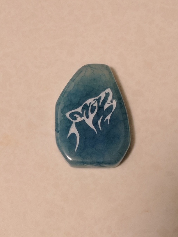
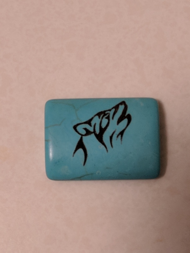
The camera certainly isn’t perfect but I have found that doing what others have said and positioning it directly under the camera helps a lot.
Here are two “beads” from Michael’s Craft Store. the stone is flat and the turquoise one is slightly rounded. That being said, both of them engraved VERY close to where I placed them with the aid of the camera.
Overall I was impressed. I look forward to seeing future improvement though… especially when it comes to the TRACE feature.
I’m not sure why you would do this, the idea behind draft board is that the barcode has that information, not just for the material, but that particular batch of material. The measurement used is Glowforges gold standard for calibration. If the calibration is off with proofgrade, and their settings, then that’s on them.
I’d also check it with the Acrylic, I think it lays a bit flatter than draft board YMMV.
It shouldn’t matter if it is entered manually or if the “proofgrade” barcode is taking care of it. However, I have no idea how accurate their barcodes even are. So lets remove one possible source of error.
Any idiot can use calipers to get the actually thickness of a material. The medium 1/8" draft board measures out to 0.133" on average.
As I was told above, apparently placement is very sensitive to thickness. As to how much? I have no idea.
But was I wrong to assume we were going to be able to place an image using the software/camera and have its reliably print where it was placed? Did I read these specs wrong?
CAMERAS
Wide Angle Camera — View of the entire laser bed
Macro Camera — Able to view one square inch with resolution of 0.002” (0.05mm)
Camera can record stills and video for documentation and sharing of projects
Optical Thickness Measurement — Optical system measures the height at various points across the material to 0.005” (0.13mm)
AUTOFOCUS
Completely Internal — Lens moves internally up and down inside the head by 0.5” (13mm)
Continuous Autofocus — Laser focal point can be changed as the head travels, following complex curves during cuts and engraves
Multipass — Focus can be shifted between engrave passes, allowing detailed depth engraves.
Focus Override — the laser can be defocused to experiment with a range of techniques that require less intense heat including acrylic bending and cooking
MISCELLANEOUS
WIFI Connectivity
110/220 VAC
50/60 HZ
Basic model is a CDRH Class I Laser Device
Pro model is a CDRH Class IV Laser Device
Positioning precision to 0.001” (0.025mm)
Engraving at 1000 DPI with 256 power levels
 ,
, and has talked about it before - she might know the reasoning behind it or the extent of off-ness or something useful.